Image pickup systems

a technology of image pickup and pickup box, which is applied in the field of image pickup system, can solve problems such as image blur and damage between lenses

Active Publication Date: 2008-01-17
ASIA OPTICAL INT LTD
View PDF3 Cites 229 Cited by
  • Summary
  • Abstract
  • Description
  • Claims
  • Application Information

AI Technical Summary

Benefits of technology

The invention is an image pickup system that uses a gyro sensor to detect changes in the device's angle and a Hall effect sensor to detect movement of the image sensor. The system integrates these signals and combines them with position information to create a combined data set. A processing module then uses this information to generate control information for a driver control unit. The driver control unit then generates a control signal to adjust the position of the image sensor. The technical effect of this invention is to improve the image pickup system's stability and accuracy by detecting and compensating for any movement or angle changes in real-time, resulting in higher quality images.

Problems solved by technology

The technical problem addressed in this patent is how to prevent blurred images caused by camera vibrations in digital cameras, without causing damage between lenses.

Method used


Image

  • Image pickup systems
  • Image pickup systems
  • Image pickup systems

Examples


Embodiment Construction

[0019]The following description is of the best-contemplated mode of carrying out the invention. This description is made for the purpose of illustrating the general principles of the invention and should not be taken in a limiting sense. The scope of the invention is best determined by reference to the appended claims.

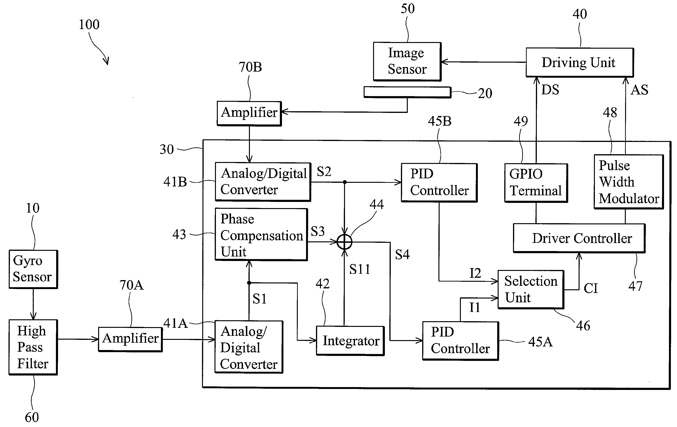
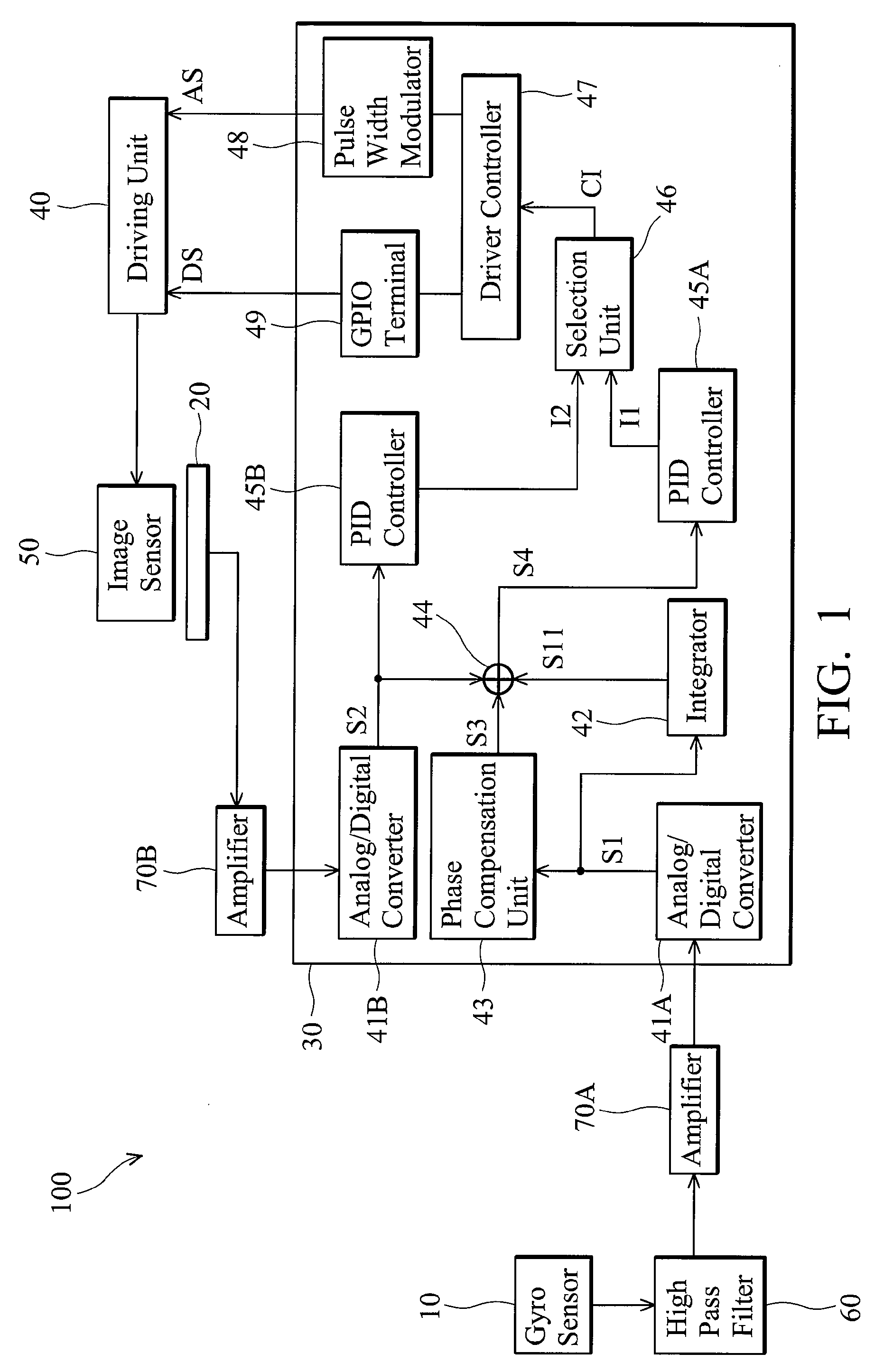
[0020]FIG. 1 shows an embodiment of an image pickup system. The image pickup system 100 can be implemented as an image pickup device with vibration compensation. An example using an image pickup system includes a digital camera but is not limited thereto. As shown, the image pickup system 100 comprises a gyro sensor 10, a Hall effect sensor 20, a processing module 30, a driving unit 40, an image sensor 50, a high pass filter 60 and amplifiers 70A and 70B.

[0021]The gyro sensor 10 can be disposed in the image pick device to detect variations in inclination and generate corresponding sensing data. For example, the gyro sensor 10 generates an angular velocity signal of the...


PUM


Abstract

Image pickup systems capable of preventing blurred images are provided, in which a first sensor detects a variation in inclination of an image pickup device to generate a first sensing data, a second sensor detects a position movement from an image sensor in the image pickup device to generate a second sensing data and a driving unit is coupled to the image sensor. A processing module receives the first and second sensing data, integrates the first sensing data, calculates the integrated first sensing data and the second sensing data to obtain control information, and enables the driving unit to adjust the position of the image sensor according to the control information.

Description


Claims


Application Information

Patent Timeline
Owner ASIA OPTICAL INT LTD
Why Eureka
Try Eureka