Unicondylar knee implants and insertion methods therefor

a knee implant and unicondylar technology, applied in the field of implants, can solve the problems of limited access to damaged joints, affecting the extent of intrusion required to complete an effective implant,

Inactive Publication Date: 2008-01-17
HOWMEDICA OSTEONICS CORP
View PDF93 Cites 40 Cited by
  • Summary
  • Abstract
  • Description
  • Claims
  • Application Information

AI Technical Summary

Benefits of technology

[0017]The kit may also include a posterior resection guide having an upper end, a lower end having an elongated opening for receiving a cutting tool and a pin opening between the upper and lower ends. The pin opening of the posterior resection guide is desirably slidable over the alignment pin. The pin opening may include a first set of pin openings and a second set of pin openings that is closer to the upper end of the posterior resection guide than the first ...

Problems solved by technology

In addition, access to damaged joints is limited and the necessity for reaching the areas...

Method used


Image

  • Unicondylar knee implants and insertion methods therefor
  • Unicondylar knee implants and insertion methods therefor
  • Unicondylar knee implants and insertion methods therefor

Examples


Embodiment Construction

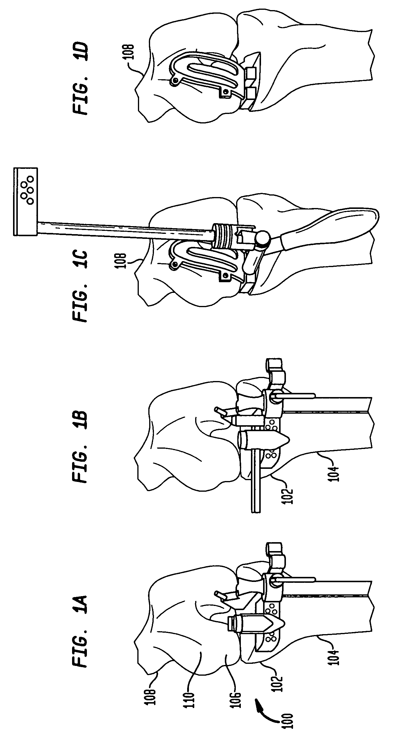
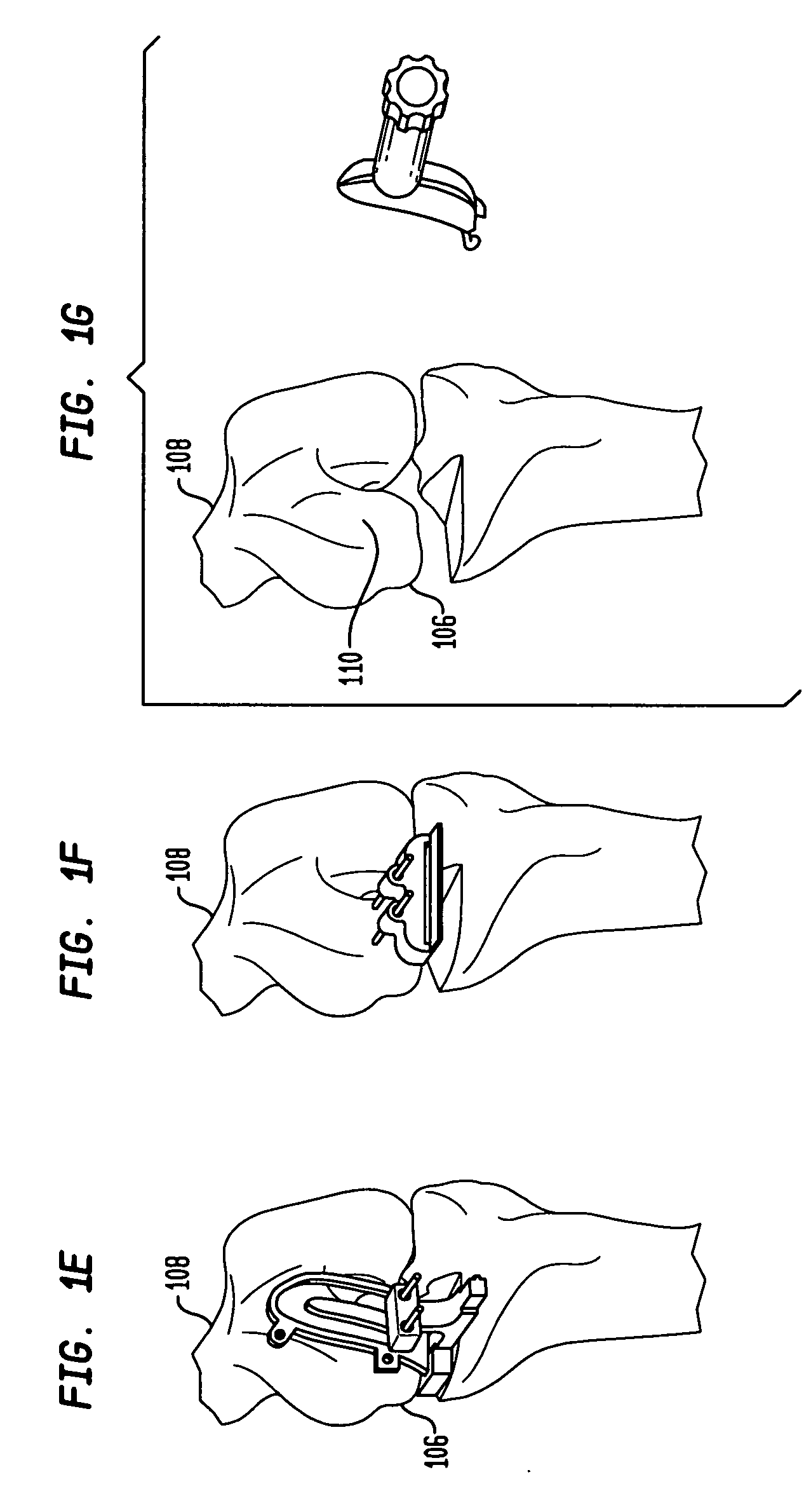
[0063]FIGS. 1A-1J show a method of preparing a knee for receiving an implant, in accordance with certain preferred embodiments of the present invention. In particular preferred embodiments, the method is used for preparing a knee to receive a knee implant such as a unicondylar knee implant. Referring to FIG. 1A, a knee joint 100 is located between a proximal end 102 of a tibia 104 and a distal end 106 of a femur 108. The distal end 106 of the femur 108 includes a distal condyle 110, which is the curved surface on a bone where it forms a joint with another bone. The femur 108 also has a posterior region of the femoral condyle.

[0064]In FIG. 1A, a tibial resection is performed on the proximal end 102 of the tibia 104. FIG. 1B shows a sagittal resection being performed on the proximal end 102 of the tibia 104. FIG. 1C shows the positioning and alignment of a combination bur template and spacer block in a knee joint. The combination bur template and spacer block includes a spacer block t...


PUM


Abstract

A system for forming keel openings in tibial bone includes a plurality of templates having different sizes, each template having a top surface, a bottom surface and a central opening extending between the top and bottom surfaces. The system includes a bone cutting instrument for forming the keel openings and a guide having a leading end that is adapted to be coupled with the templates so that the leading end of the guide is aligned with the central openings in the templates. The guide includes a plurality of slots extending toward the leading end thereof for guiding advancement of the bone cutting instrument through the central openings in the templates. Each slot is associated for use with one of the differently sized templates.

Description

CROSS REFERENCE TO RELATED APPLICATIONS[0001]The present application is a continuation of U.S. patent application Ser. No. 11 / 471,931, filed Jun. 21, 2006, the disclosure of which is hereby incorporated by reference herein.BACKGROUND OF THE INVENTION[0002]The present invention generally relates to implants and more specifically relates to method and apparatus for preparing bone for receiving an implant.[0003]The use of prosthetic implants to replace damaged natural joints, or portions of such joints, in the body has become widespread as medical and technological advances have joined to provide improved materials and configurations for prosthetic implants and innovative procedures for implanting these devices. The basic objective of such devices and procedures is to provide a repaired joint of maximum effectiveness, with a minimal intrusion into the body. Component parts of these prosthetic implants are utilized to replace portions of a natural joint which have become damaged, either...

Claims


Application Information

Patent Timeline
IPC IPC(8): A61F5/00
CPCA61B17/155A61B17/157A61F2002/3895A61F2/4684A61B17/1764
Inventor D'ALESSIO, JERRYCOLLAZO, CARLOS E.
Owner HOWMEDICA OSTEONICS CORP
Why Eureka
Try Eureka