Recirculating ball screw and nut drive

a technology of nut drive and ball screw, which is applied in the direction of gearing, gearing elements, hoisting equipment, etc., can solve the problems of complex ball deflection piece, high manufacturing and mounting costs, and reduced load-carrying capacity of the ball screw and nut drive, and achieves simple and inexpensive mounting of the ball deflection piece.

Active Publication Date: 2008-01-24
EICHENBERGER GEWINDE
View PDF6 Cites 6 Cited by
  • Summary
  • Abstract
  • Description
  • Claims
  • Application Information

AI Technical Summary

Benefits of technology

[0009]One advantage of the present invention is that the deflection head projecting on the circumference of the ball deflection piece is placed into a radially directed recess in the spindle nut body, which protects the deflection piece against twisting.
[0010]According to one embodiment of the invention, the ball deflection piece can be held in an annular recess in the spindle nut body by a snap ring. This construction can provide a simple, inexpensive mounting of the ball deflection piece.
[0011]According to one embodiment of the invention, an annular groove with a slanted orifice tapering outward is provided in the spindle nut body to hold the snap ring. This construction can provide for the natural outward movement of the ball deflection piece to be absorbed and pushed back during operation.
[0012]According to one embodiment, the present invention provides a recirculating ball screw and nut drive including a spindle, a spindle nut guided on the spindle, balls guided between the spindle and the spindle nut, in a working passage defined by grooves of the spindle and spindle nut, and deflection pieces arranged on both ends of the spindle nut to divert the balls

Problems solved by technology

However, with a large pitch of the threads, the load-carrying capacity of the ball screw and nut drive decreases with a constant length of the spindle nut, because fewer balls can engage in a load-carrying manner wit

Method used


Image

  • Recirculating ball screw and nut drive
  • Recirculating ball screw and nut drive
  • Recirculating ball screw and nut drive

Examples


Embodiment Construction

[0028]The particulars shown herein are by way of example and for purposes of illustrative discussion of the embodiments of the present invention only and are presented in the cause of providing what is believed to be the most useful and readily understood description of the principles and conceptual aspects of the present invention. In this regard, no attempt is made to show structural details of the present invention in more detail than is necessary for the fundamental understanding of the present invention, the description taken with the drawings making apparent to those skilled in the art how the several forms of the present invention may be embodied in practice.

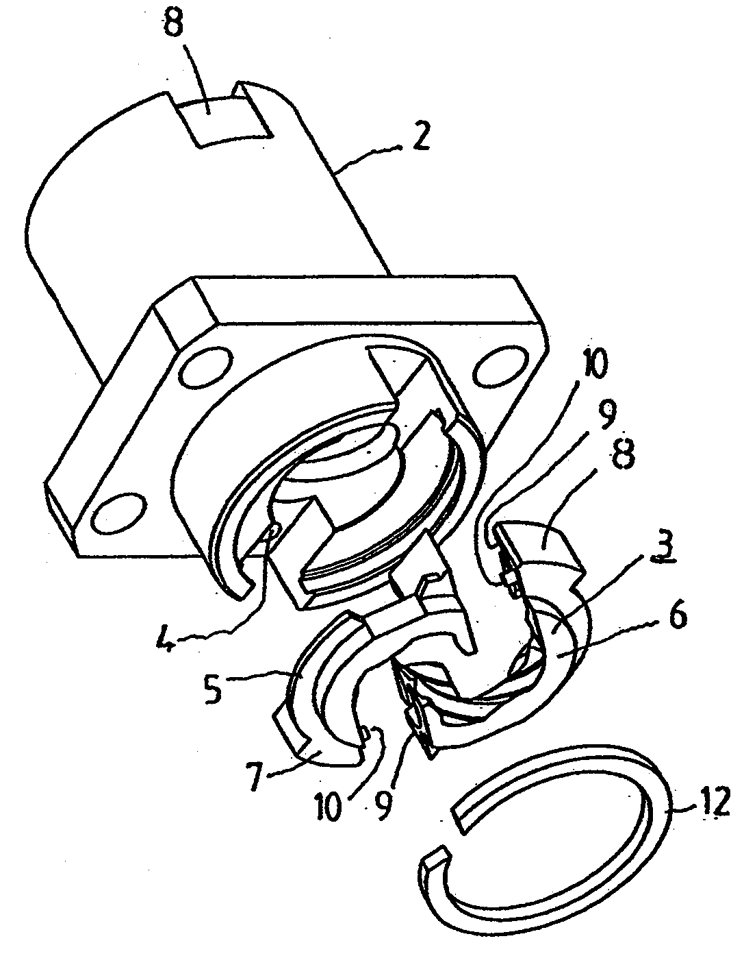
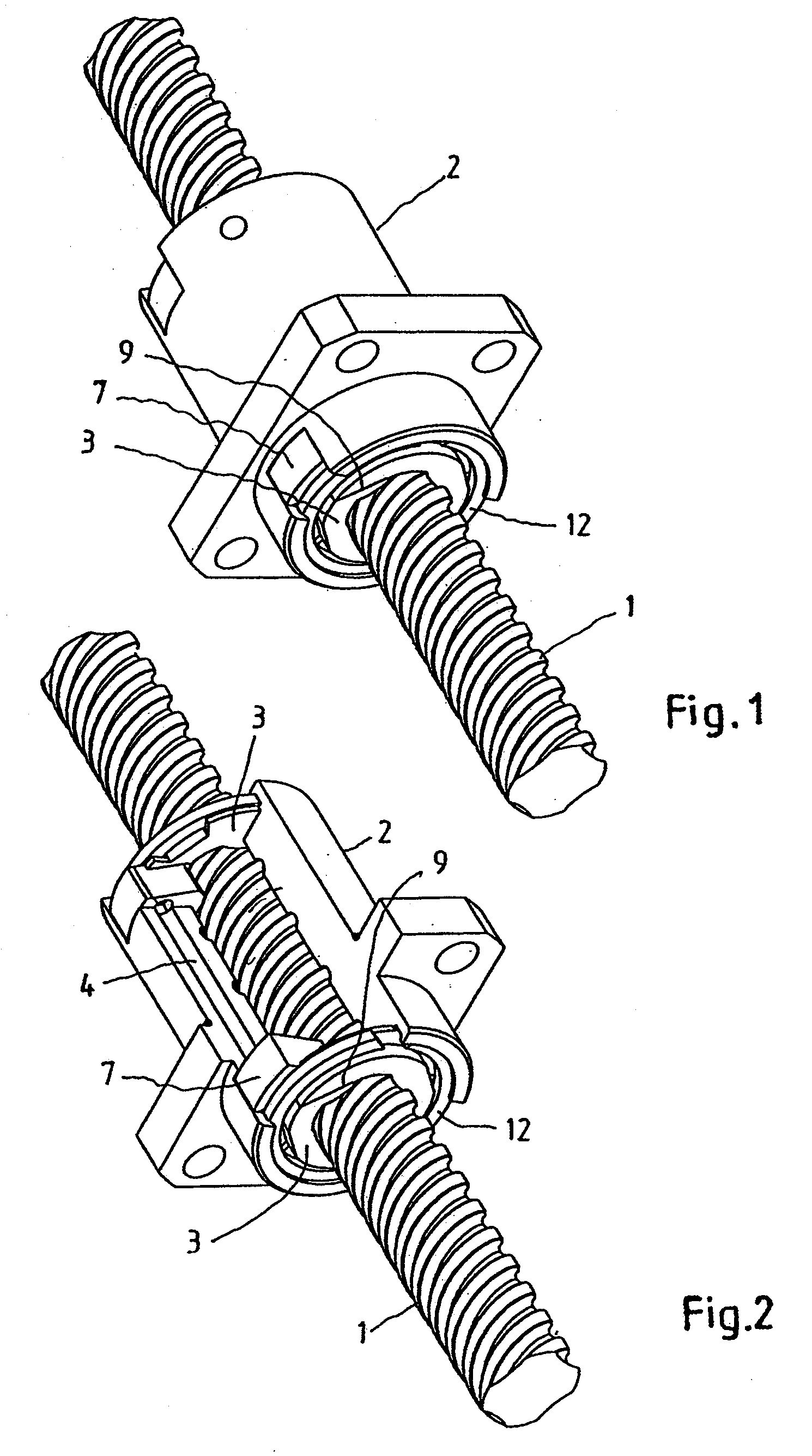
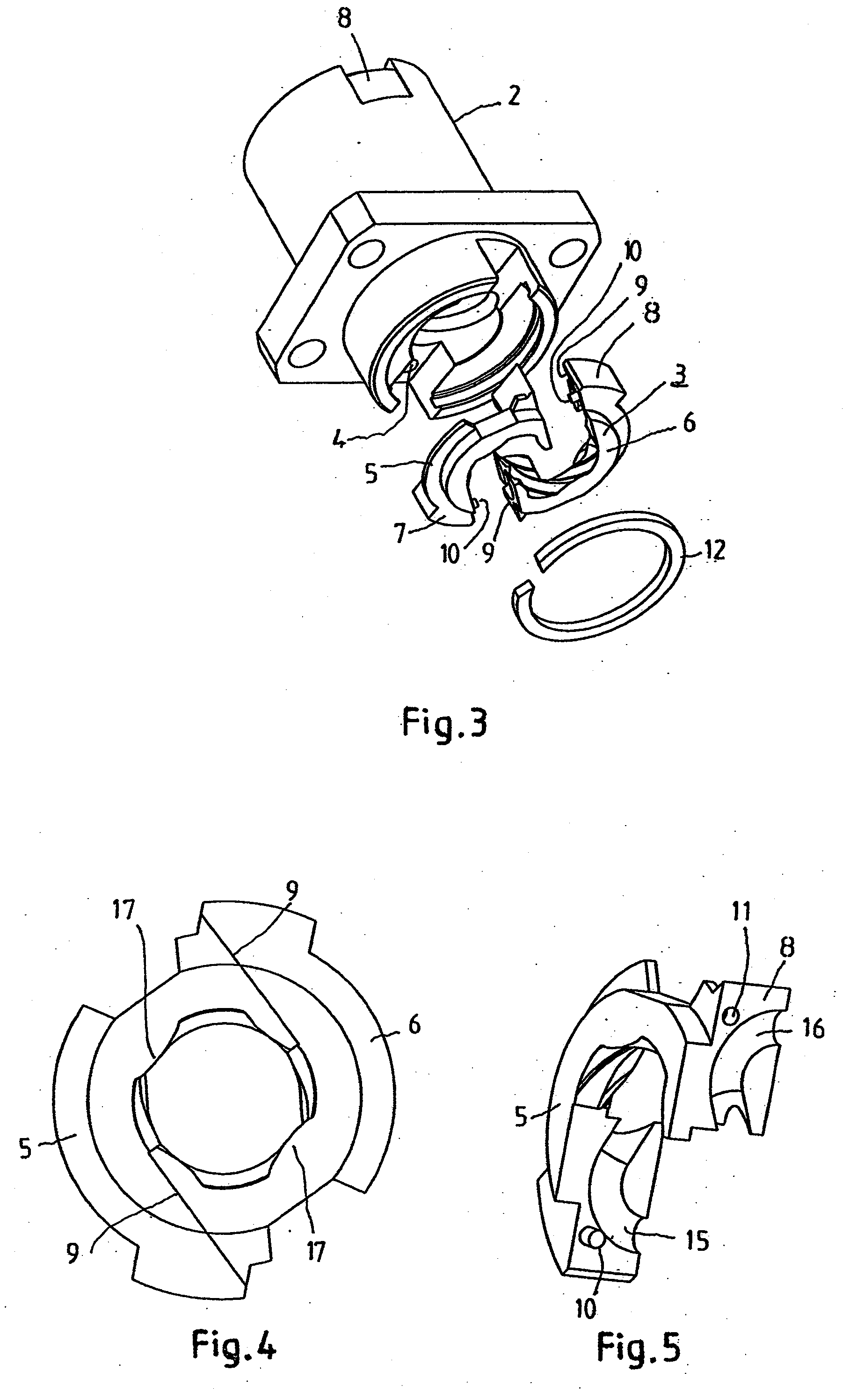
[0029]FIG. 1 shows diagrammatically a recirculating ball screw and nut drive with a spindle 1 and with a spindle nut 2 guided on the spindle. A working passage is generated between the thread grooves of the spindle 1 and the spindle nut 2, in which working passage the balls (not shown) are guided. The balls are diverted i...


PUM


Abstract

A recirculating ball screw and nut drive including a spindle, a spindle nut guided on the spindle, balls guided between the spindle and the spindle nut, in a working passage defined by grooves of the spindle and spindle nut, and deflection pieces arranged on both ends of the spindle nut to divert the balls out of the working passage into a return passage accommodated in the spindle nut, and to divert the balls out of the return passage into the working passage accommodated in the spindle nut, where the ball deflection pieces are annular and composed of at least two circular-ring sectors.

Description

CROSS-REFERENCE TO RELATED APPLICATIONS[0001]The present application claims priority under 35 U.S.C. §119 of Swiss Patent Application No. 01153 / 06, filed on Jul. 18, 2006, the disclosure of which is expressly incorporated by reference herein in its entirety.BACKGROUND OF THE INVENTION[0002]1. Field of the Invention[0003]The invention relates generally to a recirculating ball screw and nut drive with a spindle and with a spindle nut guided on the spindle, as well as with balls guided between the spindle and the spindle nut, in a working passage between their thread grooves, where the balls are diverted in ball deflection pieces on both ends of the spindle nut out of the working passage into a return passage accommodated in the spindle nut, and vice versa.[0004]2. Discussion of Background Information[0005]A recirculating ball screw and nut drive is generally disclosed in GB-PS-957330. This recirculating ball screw and nut drive includes a spindle and a spindle nut guided on the spindl...

Claims


Application Information

Patent Timeline
IPC IPC(8): F16H25/24
CPCF16H25/2219Y10T74/19753Y10T74/19772Y10T74/19749
Inventor HUSISTEIN, KURT
Owner EICHENBERGER GEWINDE
Why Eureka
Try Eureka