
Eureka
For R&D, Eureka makes reading and utilizing patents & technical documents easy.
Eureka AIR
Designed for self-driven R&D workflows. Generate viable solutions, solve complex R&D challenges, empower your innovation with AI.

Eureka Materials
Designed for material experts only. Revolutionize your material R&D, from search, analyze, to developing new materials.

TechResearch
Generate reliable direction feasibility study reports for your R&D in just a few steps.

TechSeek
Discover and master advanced knowledge NOW. Basics, ideas, possibilities, all at once.

TechMind
As an expert in R&D Theories, TechMind can generates customized viable solutions instantly.

TechRisk
Analyze your overall solution with one click, know your potential R&D risks in advance.

TechMonitor
Get weekly tech updates, stay abreast of the latest tech innovations and key insights.
Wireless receiver and wireless reception method
a wireless reception and wireless receiver technology, applied in the direction of multi-antenna systems, diversity/multi-antenna systems, orthogonal multiplexes, etc., can solve the problems of significantly deteriorating error rate characteristics in the receiving side and deteriorating error rate in the receiving side, so as to improve the error rate characteristic and interference compensation
- Summary
- Abstract
- Description
- Claims
- Application Information
AI Technical Summary
Benefits of technology
Problems solved by technology
Method used
Image

Examples
first embodiment
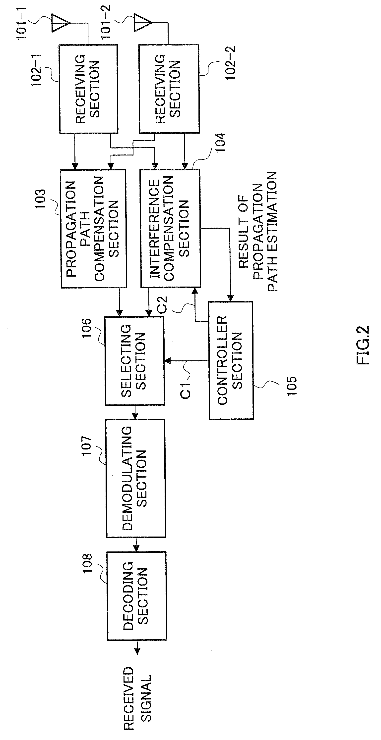
[0023]FIG. 2 is a block diagram, illustrating a configuration of a wireless receiver according to a first embodiment of the present invention.
[0024] A wireless receiver shown in FIG. 2 comprises receiving antennas 101, receiving sections 102, a propagation path compensation section 103, an interference compensation section 104, a controller section 105, a selecting section 106, a demodulating section 107 and a decoding section 108.
[0025] In FIG. 2, a receiving section 102-1 performs a predetermined wireless receiving processing such as a down-converting and the like over a signal that is received through a receiving antenna 101-1, and then output thereof to the propagation path compensation section 103 and the interference compensation section 104. Similarly, a receiving section 102-2 performs a predetermined wireless receiving processing such as a down-converting and the like over a signal that is received through a receiving antenna 101-2, and then output thereof to the propagat...
second embodiment
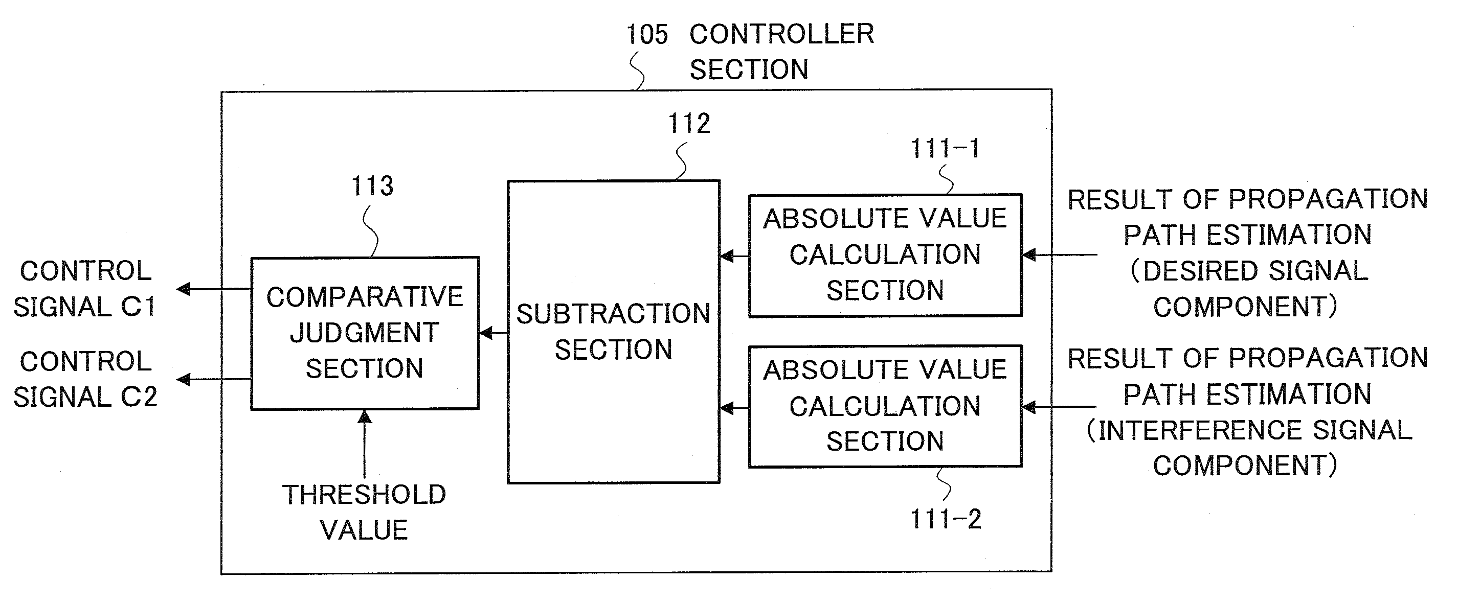
[0053]FIG. 7 is a block diagram, illustrating a configuration of a controller section of a wireless receiver according to the second embodiment of the present invention.
[0054] Here, this controller section 105a has a configuration similar to the controller section 105 shown in FIG. 2, and same numeral is referred to same element, and the description thereof is omitted. The present embodiment is characterized in that a controller section includes a threshold setting section 201.
[0055] The threshold setting section 201 is informed of a modulation level, a coding rate, a spreading factor, or a code multiplex number used for transmission signal, and sets a threshold used in the comparative judgement section 113 based on these values. For example, the QPSK modulation system has better error resistance as compared with 16QAM modulation system when the propagation path environment is deteriorated. When the QPSK is employed, by performing the propagation path compensation for the received...
PUM
 Abstract
Description
Claims
Application Information
 - R&D Engineer
- R&D Manager
- IP Professional
- Industry Leading Data Capabilities
- Powerful AI technology
- Patent DNA Extraction
Browse by: Latest US Patents, China's latest patents, Technical Efficacy Thesaurus, Application Domain, Technology Topic, Popular Technical Reports.
© 2024 PatSnap. All rights reserved.Legal|Privacy policy|Modern Slavery Act Transparency Statement|Sitemap|About US| Contact US: help@patsnap.com