Decision threshold voltage control circuit and decision threshold voltage controlling method of clock and data recovery circuit, optical receiver, and decision threshold voltage control program

a technology of threshold voltage and control circuit, which is applied in the direction of dc level restoring means or bias distortion correction, line-fault/interference reduction, and baseband system details, etc., can solve the problems of circuits and difficult to ensure the quality of transmission lines, and achieve the effect of improving the error rate characteristi

Inactive Publication Date: 2007-05-15
NEC CORP
View PDF23 Cites 7 Cited by
  • Summary
  • Abstract
  • Description
  • Claims
  • Application Information

AI Technical Summary

Benefits of technology

[0009]In order to solve the above defects, a first object of the present invention is to provide a decision threshold voltage control circuit of a decision threshold voltage feeding-capable clock and data recovery circuit and its decision threshold voltage controlling method, free from the occurrence of floor, capa...

Problems solved by technology

In the optical transmission system including an optical amplifier or WDM (wavelength division multiplexing) transmission, since a factor that deteriorates the optical waveform as mentioned above is increased, there occurs a curve in the error rate characteristic (floor) in the conventional decision circuit where the decision threshold position is fixed, which makes it difficult to assure the quality of a t...

Method used


Image

  • Decision threshold voltage control circuit and decision threshold voltage controlling method of clock and data recovery circuit, optical receiver, and decision threshold voltage control program
  • Decision threshold voltage control circuit and decision threshold voltage controlling method of clock and data recovery circuit, optical receiver, and decision threshold voltage control program
  • Decision threshold voltage control circuit and decision threshold voltage controlling method of clock and data recovery circuit, optical receiver, and decision threshold voltage control program

Examples


first embodiment

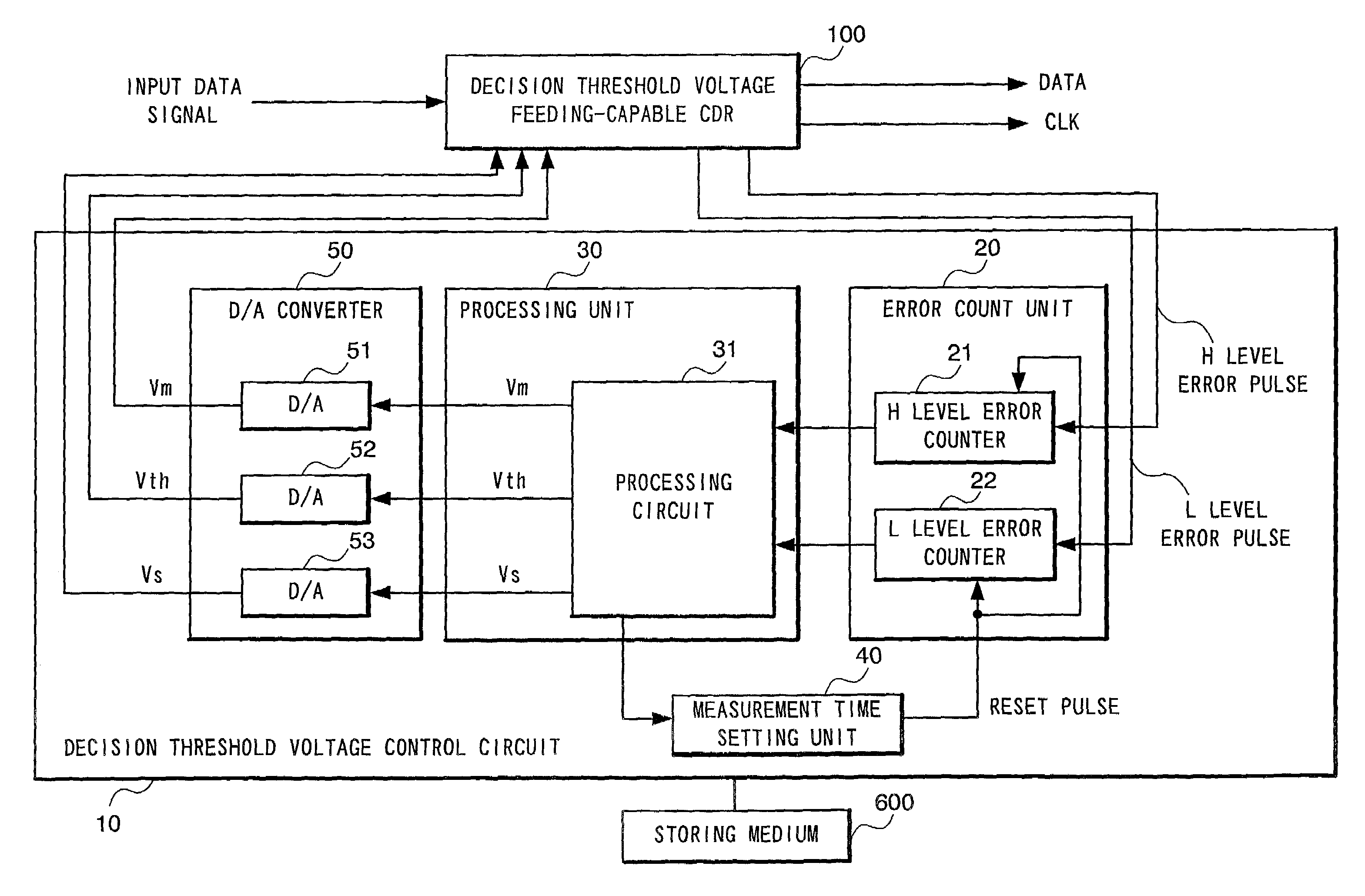
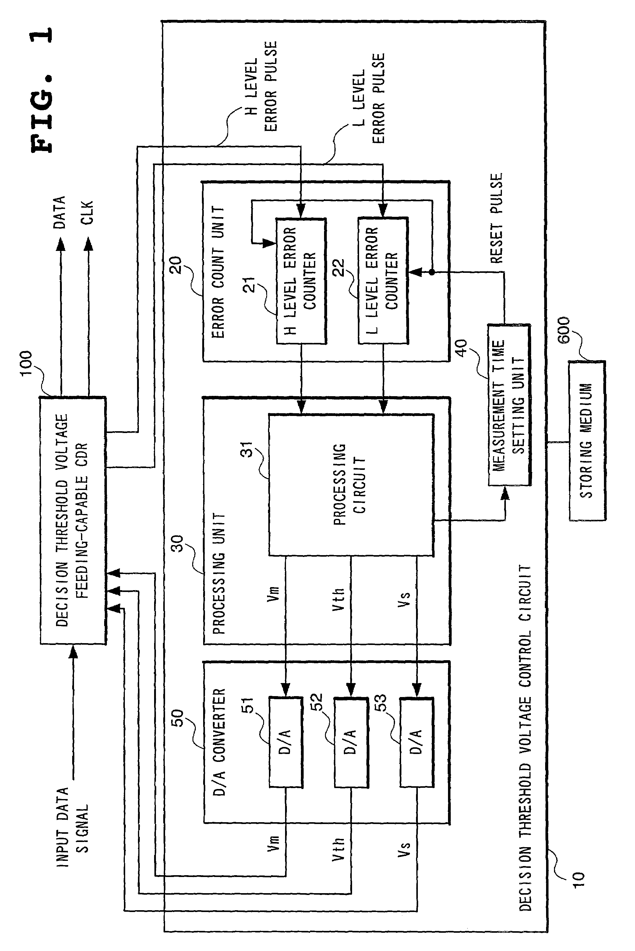
[0085]FIG. 1 is a block diagram showing the structure of a decision threshold voltage control circuit of a decision threshold voltage feeding-capable CDR according to the present invention.

[0086]In FIG. 1, the reference numeral 100 designates decision threshold voltage feeding-capable CDR (clock and data recovery circuit) in which a function of feeding a decision threshold voltage is added to CDR that converts an optical input signal into an electric signal, extracts a clock component from the input data signal amplified to a predetermined amplitude, and discriminates 1 or 0 in the input data signal at the timing of the clock, and the reference numeral 10 designates a decision threshold voltage control circuit for feeding an optimum decision threshold voltage to the CDR according to a control algorithm, in the decision threshold voltage feeding-capable CDR 100.

[0087]The decision threshold voltage feeding-capable CDR 100 has been hitherto provided, and one example of its structure is...

second embodiment

[0132]In the decision threshold voltage control circuit 10 the central decision point voltage Vth is set at any point fixed between the upper decision point Vm and the lower decision point Vs by the processing unit 30. More specifically, after conversion into analog voltage, the central decision point voltage Vth is set at any point between the upper decision point voltage Vm and the lower decision point voltage Vs by using a voltage divider 60.

[0133]A third embodiment of the present invention will be described. FIG. 13 is a view showing the structure of the decision threshold voltage control circuit according to the third embodiment of the present invention, FIG. 14 a view showing the basic concept of a control algorithm according to the third embodiment, and FIG. 15 is one example of a flow chart using the control algorithm according to the third embodiment.

[0134]The third embodiment is constituted in that a fixed measurement time is set in the measurement time setting unit 40a, ...

fifth embodiment

[0140]The decision threshold voltage control circuit 10A comprises a D / A converter 50A for converting the H level error pulses and the L level error pulses into the direct current voltages depending on the numbers of the respective level errors and a processing unit 30A. The processing unit 30A includes operational amplifiers 301A and 302A and the D / A converter 50A includes average value detecting circuits 501A to 503A and an OR-circuit 504A.

[0141]The operation of the decision threshold voltage control circuit 10A will be described with reference to FIG. 21. In the D / A converter 50A, the average value detecting circuit 501A converts the H level error pulses into the direct current voltages (H level error voltage Cm) depending on the number of the same error pulses, the average value detecting circuit 502A converts the L level error pulses into the direct current voltages (L level error voltage Cs) depending on the number of the same error pulses, and the average value detecting cir...


PUM


Abstract

According to a decision threshold voltage controlling method of feeding an optimum decision threshold voltage to a clock and data recovery circuit which converts an optical input signal into an electric signal, extracts a clock component from an input data signal amplified to a predetermined amplitude, and identifies 1 or 0 in the input data signal at a timing of the clock, three decision points are suitably controlled, by selectively performing a process of controlling the spaces of the three decision points, a process of moving the three decision points with their spaces kept as they are, and a process of changing an error pulse measurement time, depending on a measurement result of the error pulse.

Description

BACKGROUNDS OF THE INVENTION[0001]1. Field of the Invention[0002]The present invention relates to a control circuit for feeding an optimum decision threshold voltage to a clock and data recovery circuit, a decision threshold voltage controlling method, and a decision threshold voltage control program in the clock and data recovery circuit with a function of feeding a decision threshold voltage.[0003]2. Description of the Related Art[0004]In a recent optical transmission system including an optical amplifier or WDM (Wavelength Division Multiplexing) transmission technique, a factor that deteriorates an optical waveform is increased much more than in the conventional optical transmission system. The factor includes, by way of example, accumulation of noises caused by ASE (amplified spontaneous emission) by an optical amplifier, waveform distortion caused by dispersion and nonlinear effects in an optical fiber, which remarkably affects the quality of optical transmission with an increa...

Claims


Application Information

Patent Timeline
IPC IPC(8): H04L25/06H03D1/04H04L25/03H04L7/02H04L7/033H04L25/02
CPCH04B10/695H04L25/063H04L7/033
Inventor MATSUMOTO, YOSHIHIROKURIYAMA, TAKASHIINAMI, DAIJIROUSHIRAIWA, MASAKI
Owner NEC CORP
Why Eureka
Try Eureka