
Reptile lamp having direction adjustable function

Inactive Publication Date: 2008-02-07
CHEN MING CHIH
View PDF7 Cites 5 Cited by
  • Summary
  • Abstract
  • Description
  • Claims
  • Application Information

AI Technical Summary

Benefits of technology

[0007]Another objective of the present invention is to provide a reptile lamp, wherein the electric bulb is rotatable relative to the support bracket in a two-directional way so as to adjust the angle and direction of the electric bulb freely, thereby enhancing the light effect of the electric bulb.
[0008]A further objective of the present invention is to provide a reptile lamp, wherein the user only needs to operate the control knob to control the direction of the electric bulb, so that the direction of the electric bulb is controlled easily and quickly, thereby facilitating the user manipulating the control knob.

Problems solved by technology

However, the electric bulb is fixed in the lamp shade and cannot be turned to change its orientation, so that the light emitted from the electric bulb is directed toward a constant direction and cannot be projected onto the whole body of the pet in the pet cage, thereby limiting the function of the reptile lamp.

Method used


Image

  • Reptile lamp having direction adjustable function
  • Reptile lamp having direction adjustable function
  • Reptile lamp having direction adjustable function

Examples


Embodiment Construction

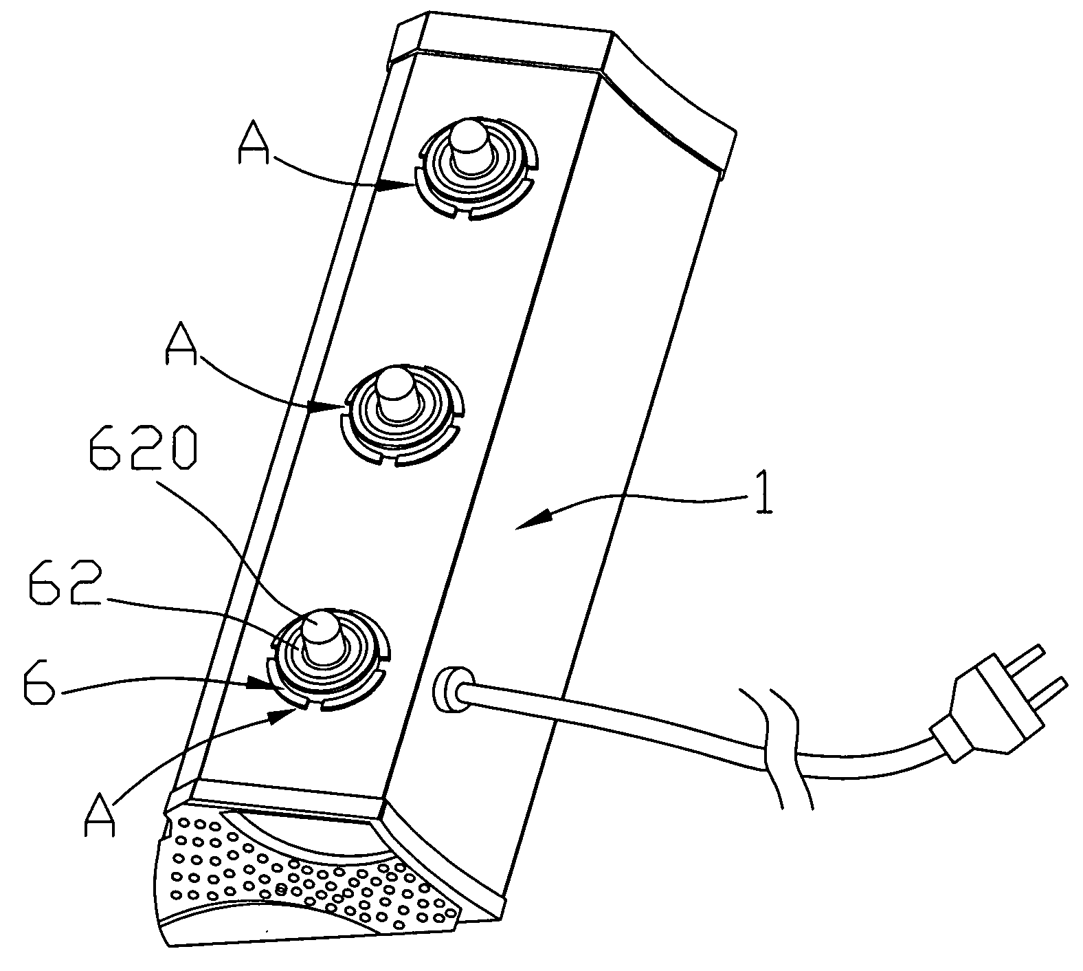
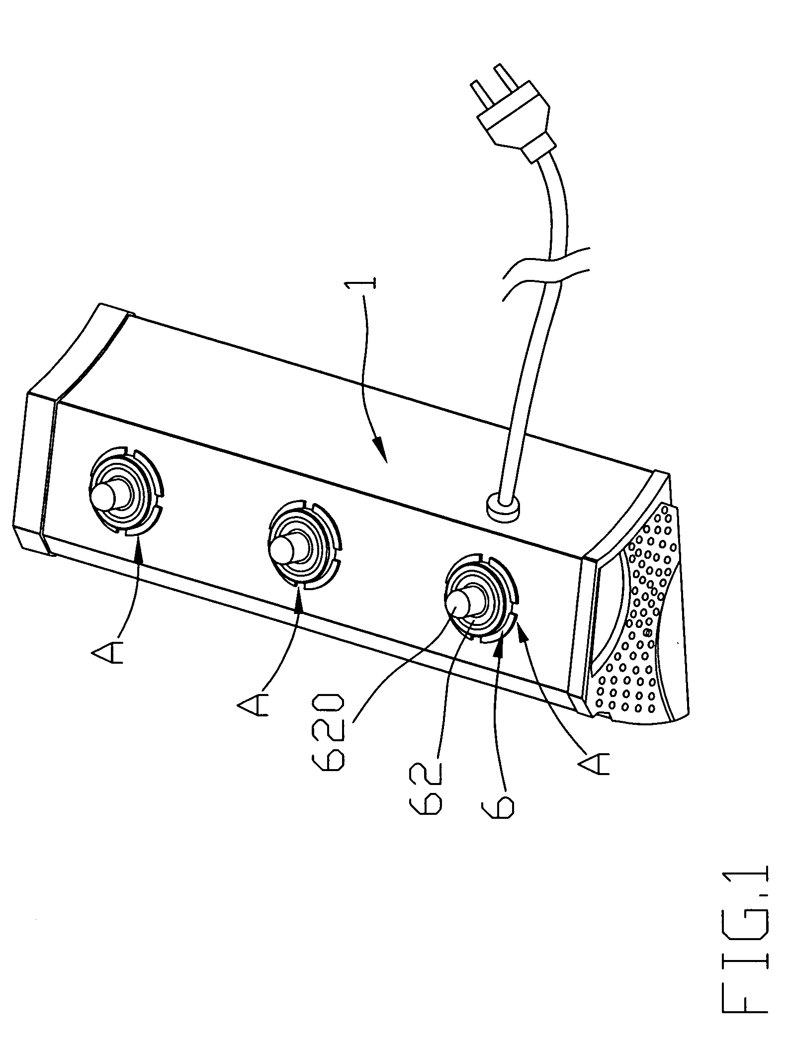
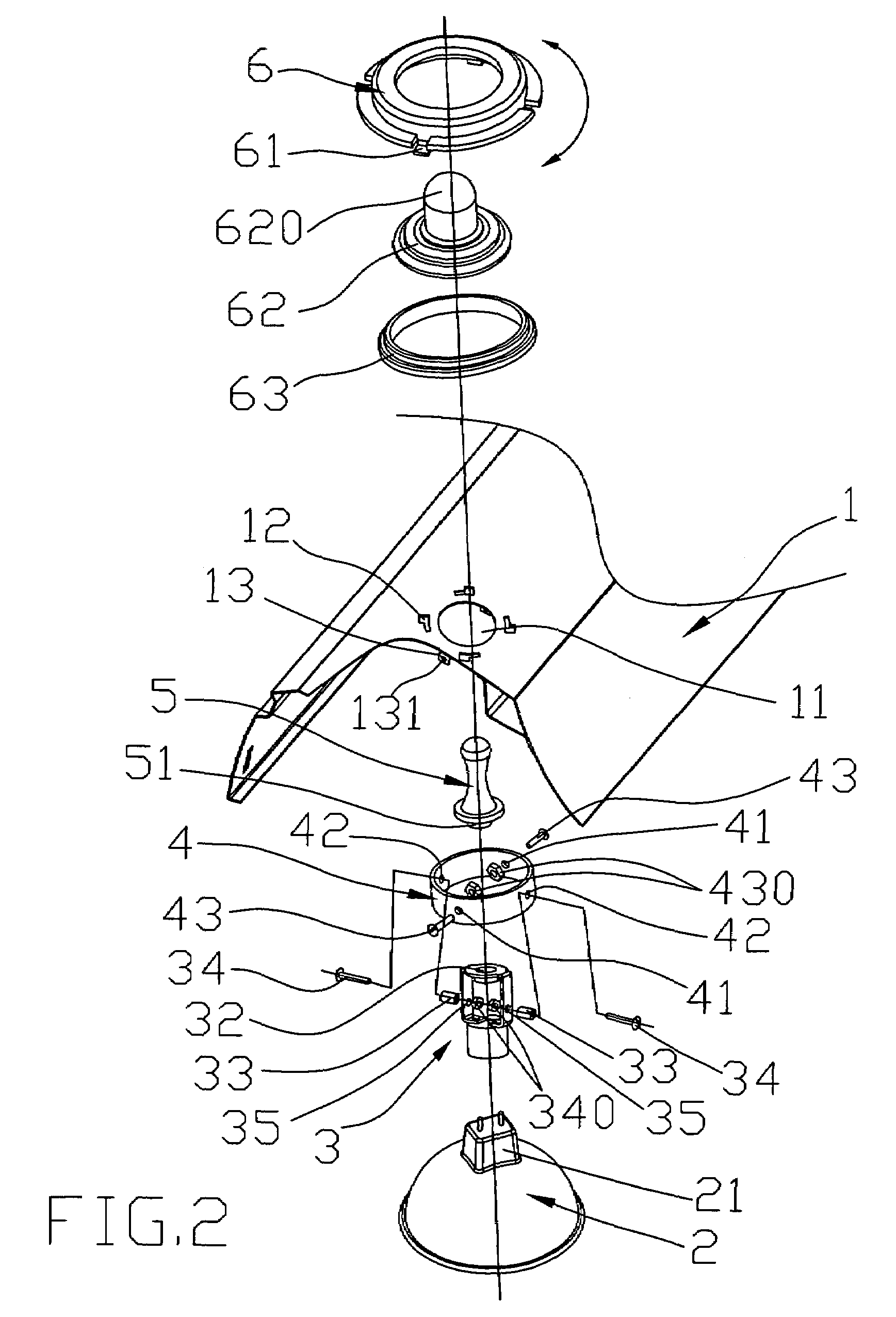
[0017]Referring to the drawings and initially to FIGS. 1-4, a reptile lamp in accordance with the preferred embodiment of the present invention comprises a support bracket 1, and at least one angle adjustable device “A” mounted on the support bracket 1.

[0018]The support bracket 1 has an elongated shape and has a substantially inverted U-shaped cross-sectional profile. The support bracket 1 has a top wall having an inner face provided with two support plates 13 each formed with a through holes 131. The top wall of the support bracket 1 is formed with a passage 11 and a plurality of locking slots 12 surrounding the passage 11.

[0019]The angle adjustable device “A” includes a pivot ring 4 pivotally mounted on the support bracket 1, a socket 3 pivotally mounted in the pivot ring 4, an electric bulb 2 mounted on the socket 3 to move therewith, a control knob 5 secured on the socket 3 to drive the socket 3 and the pivot ring 4 and partially protruded outwardly from the support bracket 1, a...


PUM


Abstract

A reptile lamp includes a support bracket, and at least one angle adjustable device. The angle adjustable device includes a pivot ring pivotally mounted on the support bracket, a socket pivotally mounted in the pivot ring, and an electric bulb mounted on the socket to move therewith. Thus, the electric bulb is rotatable relative to the support bracket in a two-directional way so as to adjust the angle and direction of the electric bulb freely, thereby enhancing the light effect of the electric bulb. In addition, the user only needs to operate the control knob to control the direction of the electric bulb, so that the direction of the electric bulb is controlled easily and quickly, thereby facilitating the user manipulating the control knob.

Description

BACKGROUND OF THE INVENTION[0001]1. Field of the Invention[0002]The present invention relates to a reptile lamp, and more particularly to a reptile lamp for a pet cage to project a light onto the reptile on the body of the pet in the pet cage.[0003]2. Description of the Related Art[0004]A conventional reptile lamp for a pet cage comprises a lamp shade, and an electric bulb mounted in the lamp shade. Thus, the electric bulb emits a light which is projected onto the reptile on the body of the pet in the pet cage. However, the electric bulb is fixed in the lamp shade and cannot be turned to change its orientation, so that the light emitted from the electric bulb is directed toward a constant direction and cannot be projected onto the whole body of the pet in the pet cage, thereby limiting the function of the reptile lamp.BRIEF SUMMARY OF THE INVENTION[0005]In accordance with the present invention, there is provided a reptile lamp, comprising a support bracket, and at least one angle ad...

Claims


Application Information

Patent Timeline
IPC IPC(8): F21V15/00
CPCF21V21/30A01K63/06
Inventor CHEN, MING-CHIH
Owner CHEN MING CHIH
Learn More