Connector

Inactive Publication Date: 2008-02-07
HIROSE ELECTRIC GROUP
View PDF3 Cites 22 Cited by
  • Summary
  • Abstract
  • Description
  • Claims
  • Application Information

AI Technical Summary

Benefits of technology

[0023]According to the present invention, the fitting lock piece is held only with the metal shell

Problems solved by technology

Accordingly, the conventional connector tends to have a co

Method used


Image

  • Connector
  • Connector
  • Connector

Examples


Embodiment Construction

[0029]Hereunder, embodiments of the present invention will be explained with reference to the accompanying drawings. In the explanation below, an electrical connector is used as an example. However, the present invention is not limited to the electrical connector, and may be applicable to, for example, an optical connector and the like. Accordingly, the present invention is not limited to the electrical connector.

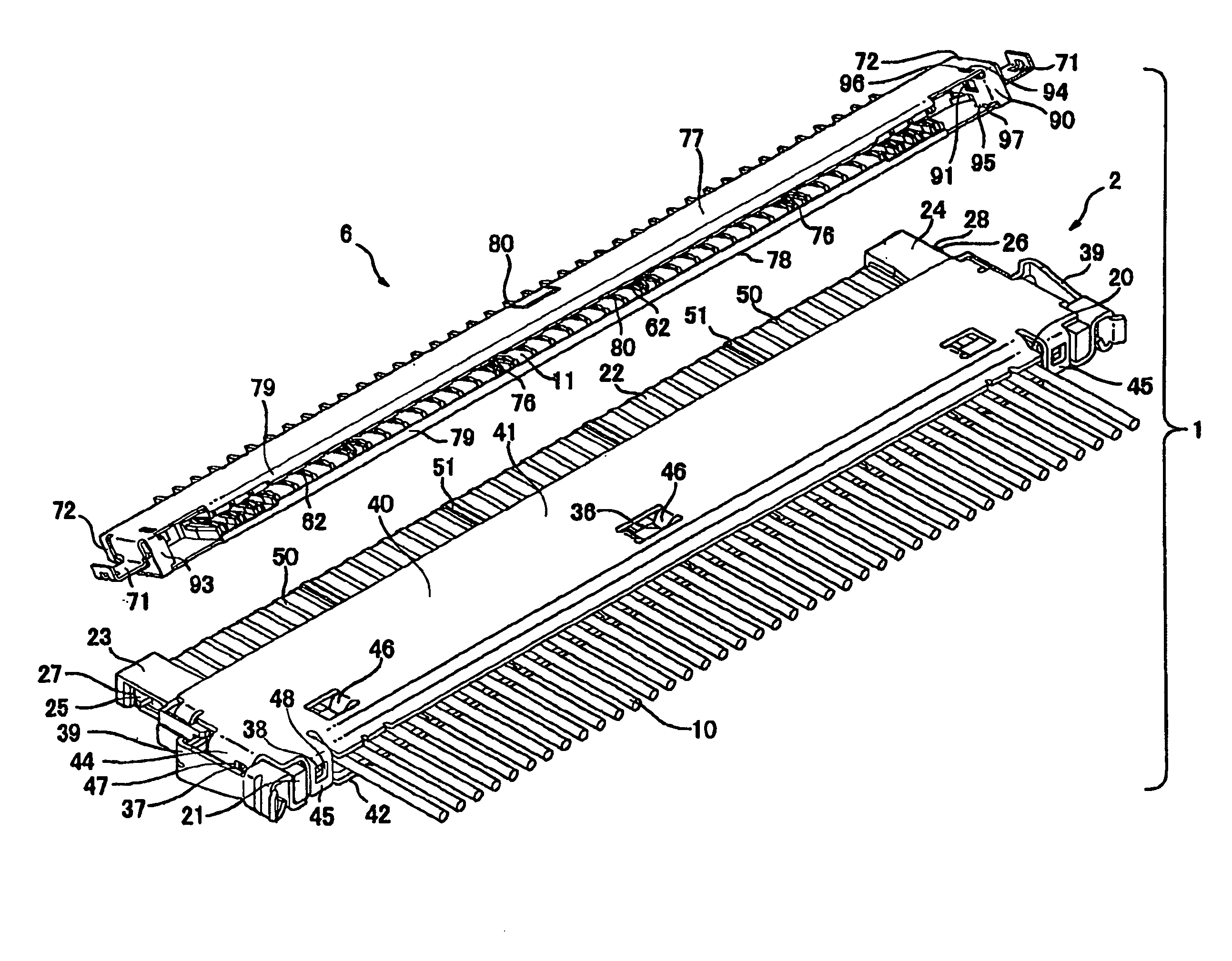
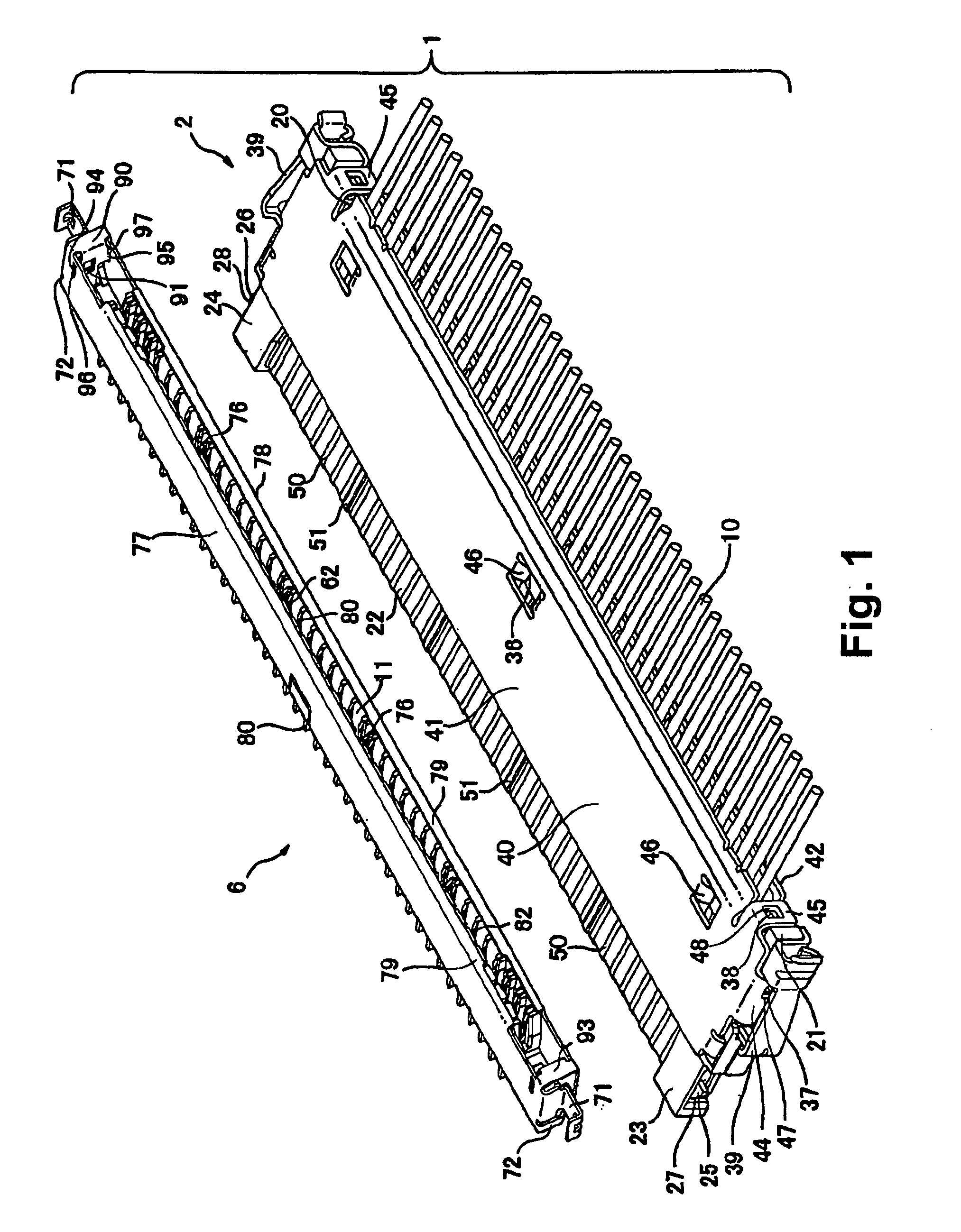
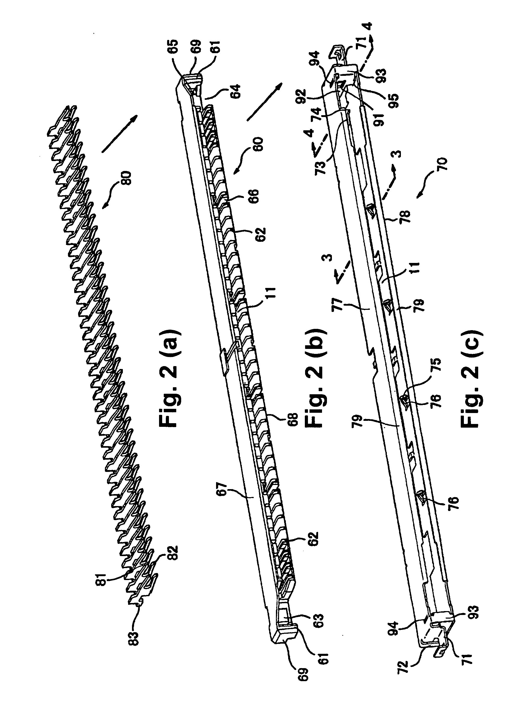
[0030]FIG. 1 is an upper surface perspective view of an electrical connector 1 according to an embodiment of the invention. FIGS. 2(a) to 2(c) are exploded perspective views of a receptacle connector 6. FIG. 3 is a sectional view taken along a line 3-3 in FIG. 2(c). FIG. 4 is a sectional view taken along a line 4-4 in FIG. 2(c).

[0031]The electrical connector 1 comprises a detachable plug connector (for cable connection) 2 and the receptacle connector (for board connection) 6. In operation, for instance, a receptacle connector 6 is fixed to a board. As clearly shown in FIG. ...


PUM


Abstract

A connector is provided with a lock mechanism for locking with a mating connector when the mating connector is fitted in the connector. The connector includes a housing and a metal shell for covering an upper surface, a lower surface, and side surfaces of the housing. The metal shell includes a fitting lock piece on a side portion of a fitting opening, and the fitting lock piece is arranged along a fitting direction with respect to the mating connector. The fitting lock piece includes a corresponding lock member for locking with a locking member of the mating connector when the mating connector is fitted in the connector through the fitting opening. The fitting lock piece engages an upper plate and a lower plate of the metal shell covering the upper surface and the lower surface of the housing, respectively.

Description

BACKGROUND OF THE INVENTION[0001]The present invention relates to a connector to be connected to a mating connector. More specifically, the present invention relates to a connector having a lock mechanism for locking a mating connector when the connector is connected to the mating connector.[0002]Patent Reference has disclosed a conventional connector having a lock mechanism. FIG. 5 is a partially sectional perspective view showing the lock mechanism of the conventional connector disclosed in patent Reference.Patent Reference Japanese Patent Publication No. 2004-327168[0003]The conventional connector is formed of a plug connector 100 and a receptacle connector 110. As shown in FIG. 5, the plug connector 100 has a lock lever 145 at a right front edge thereof, and the receptacle connector 110 has a lock mechanism at a right front edge thereof. Note that each of the plug connector 100 and the receptacle connector 110 has a shape symmetrical relative to a longitudinal direction thereof....

Claims


Application Information

Patent Timeline
IPC IPC(8): H01R13/627
CPCH01R13/5045H01R13/6593H01R13/6582H01R13/639
Inventor FUKUSHIMA, TAKESHI
Owner HIROSE ELECTRIC GROUP
Why Eureka
Try Eureka