
Shirt finishing machine

a technology of shirt finishing machine and shirt, which is applied in the direction of clothes making apparatus, textiles and paper, washing apparatus, etc., can solve the problem that the sleeves cannot be finished clean, and achieve the effect of eliminating completely the troublesome operation and positive

Active Publication Date: 2008-02-14
SANKOSHA ENGINEERING CO LTD
View PDF9 Cites 3 Cited by
  • Summary
  • Abstract
  • Description
  • Claims
  • Application Information

AI Technical Summary

Benefits of technology

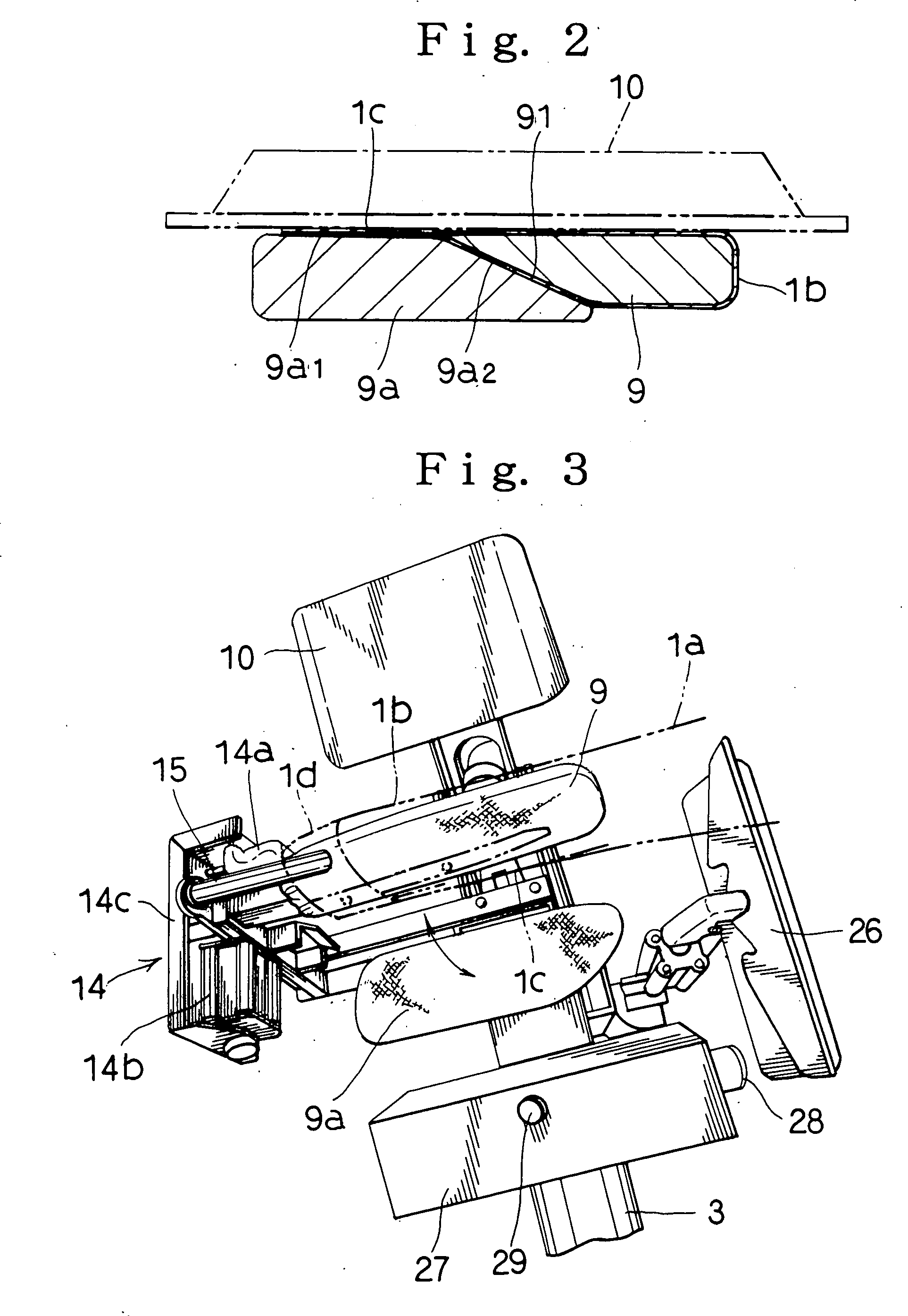
[0010]Accordingly, in accordance with the present invention, since the sleeves can be pulled under a state in which the lower surfaces of the extremity ends of the sleeves are being pressed with the movable irons and the shirt can be finished in tension by hot air and the like, it is possible to prevent some wrinkles from being applied to the lower surfaces of the extremity ends of the sleeves and finish the sleeves clean.
[0026]The present invention eliminates such problems as above. Accordingly, in accordance with the present invention, it is possible to eliminate completely the troublesome operation in which the tension applying distance of the trunk tension member must be selected in compliance with the size and it can be positively performed without being influenced by a worker's judgment. In this case, the front part of the shirt is adsorbed against the torso by applying front buttons or discharging inside the torso. This is applied to prevent the front bodice of the shirt from being worn out at a skin by the tension applying work of the trunk tension member. The trunk tension member is arranged to move up to a position where it is inclined by its own weight, through manual operation, and its returning-back operation is usually carried out automatically by an air cylinder and the like.

Problems solved by technology

Accordingly, this type of prior art finishing machine had a problem that the lower surfaces of the extremity ends of the sleeves are pulled apart, some wrinkles are generated at these locations and the sleeves cannot be finished clean.

Method used


Image

  • Shirt finishing machine
  • Shirt finishing machine
  • Shirt finishing machine

Examples


Embodiment Construction

[0039]Referring now to the drawings, the preferred embodiments of the present invention will be described.

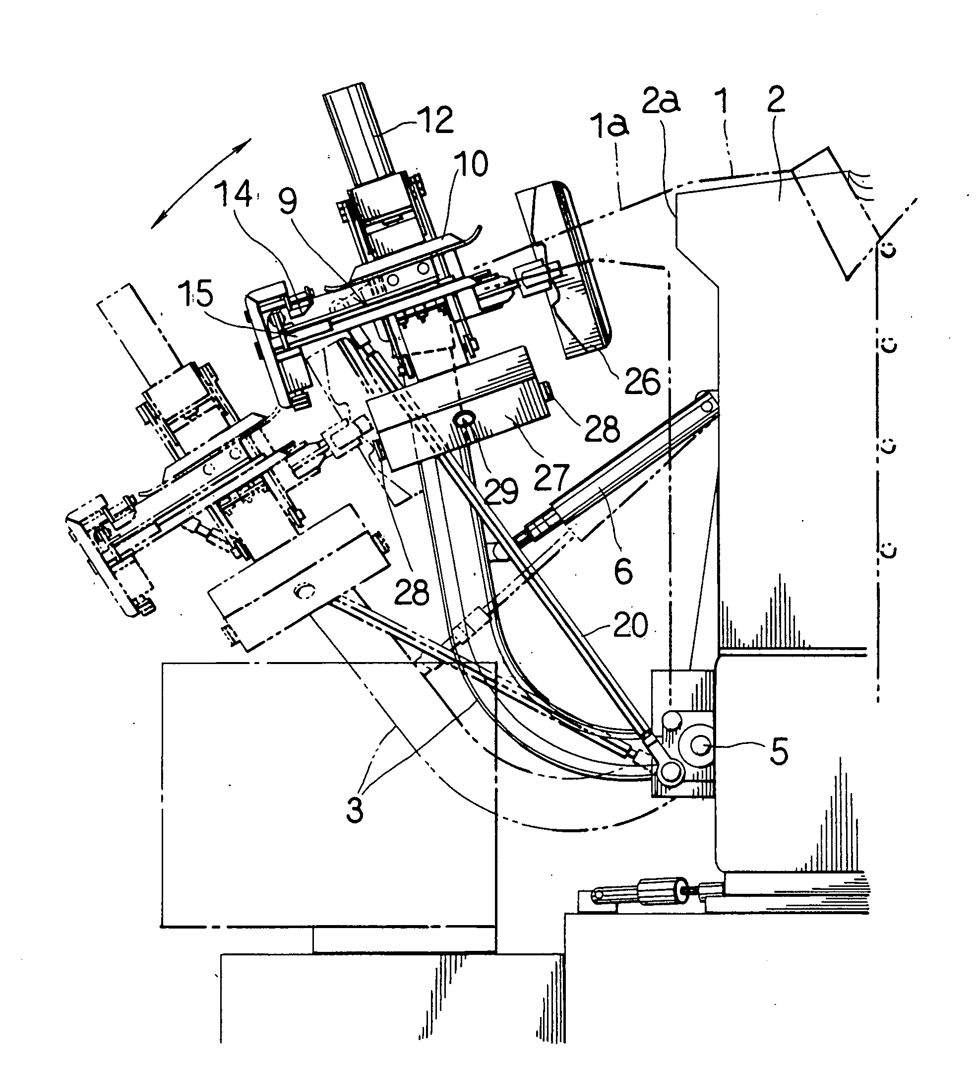
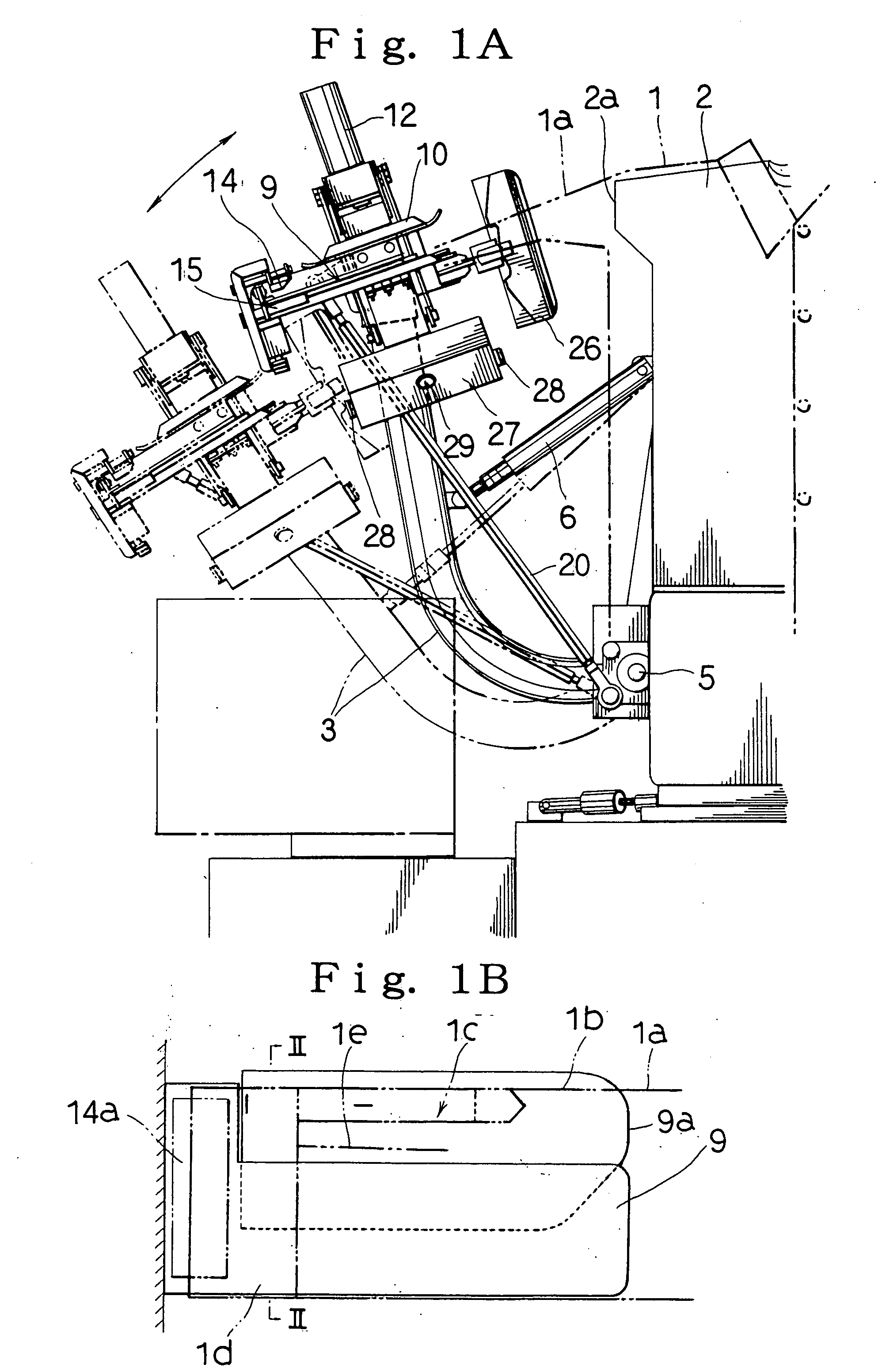
[0040]The present invention is formed to comprise a torso 2 for covering a shirt 1 such as a white shirt (a torso similar to the upper part of a human body) and a pair of right and left supporting arms 3 arranged at both sides of the torso 2, inclined to the side of the torso 2 for tensioning a sleeve 1a of the shirt 1. Inside part of the torso 2 is evaporated and the front bodice of the shirt 1 is formed to be adsorbed against the surface of the torso 2. In addition, the shirt finishing machine of the present invention is formed to enable both steam and hot air to be supplied from inside of the torso 2 into the sleeve 1a of the shirt 1 through a shoulder 2a.

[0041]The lower ends of the supporting arms 3 are fixed to both sides of a column 4 (refer to FIG. 11) raised at the rear side of the torso 2 through a shaft 5 extending along a forward or rearward direction of the torso 2....


PUM


Abstract

A shirt finishing machine includes a torso 2 for putting on a shirt 1 and a pair of right and left supporting arms 3. The upper part of the supporting arm 3 is provided with a lower iron 9 for setting an extremity end 1b of a sleeve 1a, a fixing instrument 14 for fixing a cuff 1d of the sleeve 1a to the lower iron 9, and an upper iron 10 for pressing against an upper surface of the lower iron 9 and for press finishing the extremity end 1b of the sleeve 1a. A movable iron 9a presses a lower surface of the extremity end 1b of the sleeve 1a inserted into the lower iron 10 at the time of pressing with the upper iron 10.

Description

BACKGROUND OF INVENTION[0001]1. Field of Invention[0002]This invention relates to a shirt finishing machine for use in press finishing a shirt such as a washed white shirt and the like, and more particularly a shirt finishing machine formed to enable wrinkles to be eliminated under a state in which the shirt is put on a torso.[0003]2. Description of Related Art[0004]As this type of prior art shirt finishing machine, there has been provided the machine described in the gazette of U.S. Pat. No. 6,758,377, for example. This type of prior art shirt finishing machine comprises a torso for putting on a shirt, a pair of right and left supporting arms arranged at both sides of the torso and inclined toward the sides of the torso to pull the sleeves of the shirt. Then, the upper portions of the supporting arms are provided with a lower iron to which the extremity end of the sleeve is set, clamp devices for use in fixing the cuffs of the sleeves to the lower iron and an upper iron for use in ...

Claims


Application Information

Patent Timeline
Patent Type & Authority Applications(United States)
IPC IPC(8): D06C15/00
CPCD06F71/20
Inventor UCHIKOSHI, MITSUYUKI
Owner SANKOSHA ENGINEERING CO LTD
Learn More