
Digital video surveillance system

a video surveillance and digital technology, applied in the field of digital video surveillance systems, can solve the problems of reducing the convenience of employing such devices, requiring extensive wiring and cabling, and large size of the surveillance system, and achieve the effect of removing the often poor quality of frequency transmission

Inactive Publication Date: 2008-02-14
MARCHE DESIGNS
View PDF2 Cites 148 Cited by
  • Summary
  • Abstract
  • Description
  • Claims
  • Application Information

AI Technical Summary

Benefits of technology

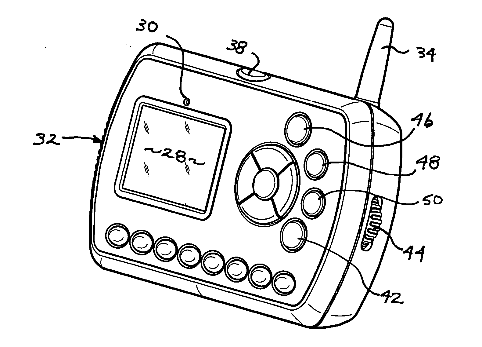
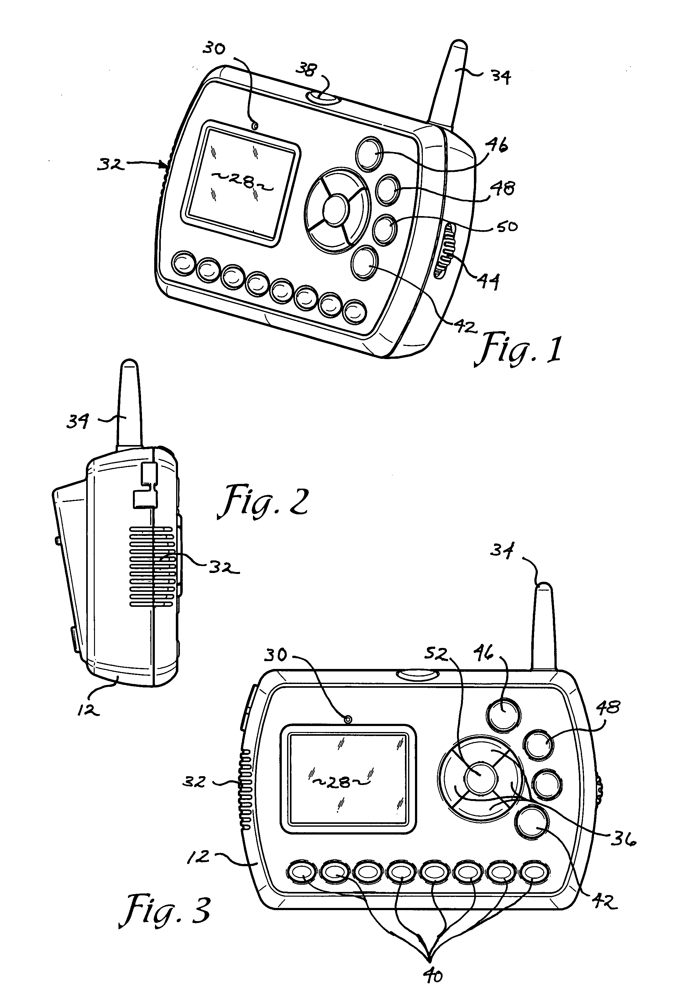
[0010] The central control unit 12 may be mounted in a fixed location or may be carried about the home by the individual during the performance of tasks or movement from one location to another. The central observation unit or base unit is in wireless communication with the accessory units and may be hard wired or battery operated to allow user selectability of mobile or fixed location use of the base unit. The sentry positioned and fixed locations and transmit data digitally to the central or base unit thereby eliminating the often poor grade or frequency transmission quality of analog signals used in past devices. In addition, the wireless nature of the present system avoids the need for preplanning of installation or extensive or expensive reconfiguration of existing homes to accommodate the surveillance.

Problems solved by technology

Heretofore, such surveillance systems have generally been large and cumbersome and required extensive wiring and cabling between the locations to be monitored and a central monitoring device.
This level of complication has substantially reduced the convenience of employing such devices and limited the homes in which such devices could be employed to those in which either pre-planning during construction was involved for including such devices or extensive modification of the pre-existing home was made to accommodate such devices.
A further limitation of such previous devices has been the limited ability to monitor the incoming signals from the various accessory devices from various locations of the home.
If the home owner was at a distance from the central monitoring device, the home owner may be unaware that an intruder or visitor was near the home where it may not be able to arrive at the vicinity of the central control device until after the visitor had left or the intruder initiated undesirable behavior.

Method used


Image

  • Digital video surveillance system
  • Digital video surveillance system
  • Digital video surveillance system

Examples


Embodiment Construction

[0025] As required, detailed embodiments of the present inventions are disclosed herein; however, it is to be understood that the disclosed embodiments are merely exemplary of the invention, which may be embodied in various forms. Therefore, specific structural and functional details disclosed herein are not to be interpreted as limiting, but merely as a basis for the claims and as a representative basis for teaching one skilled in the art to variously employ the present invention in virtually any appropriately detailed structure.

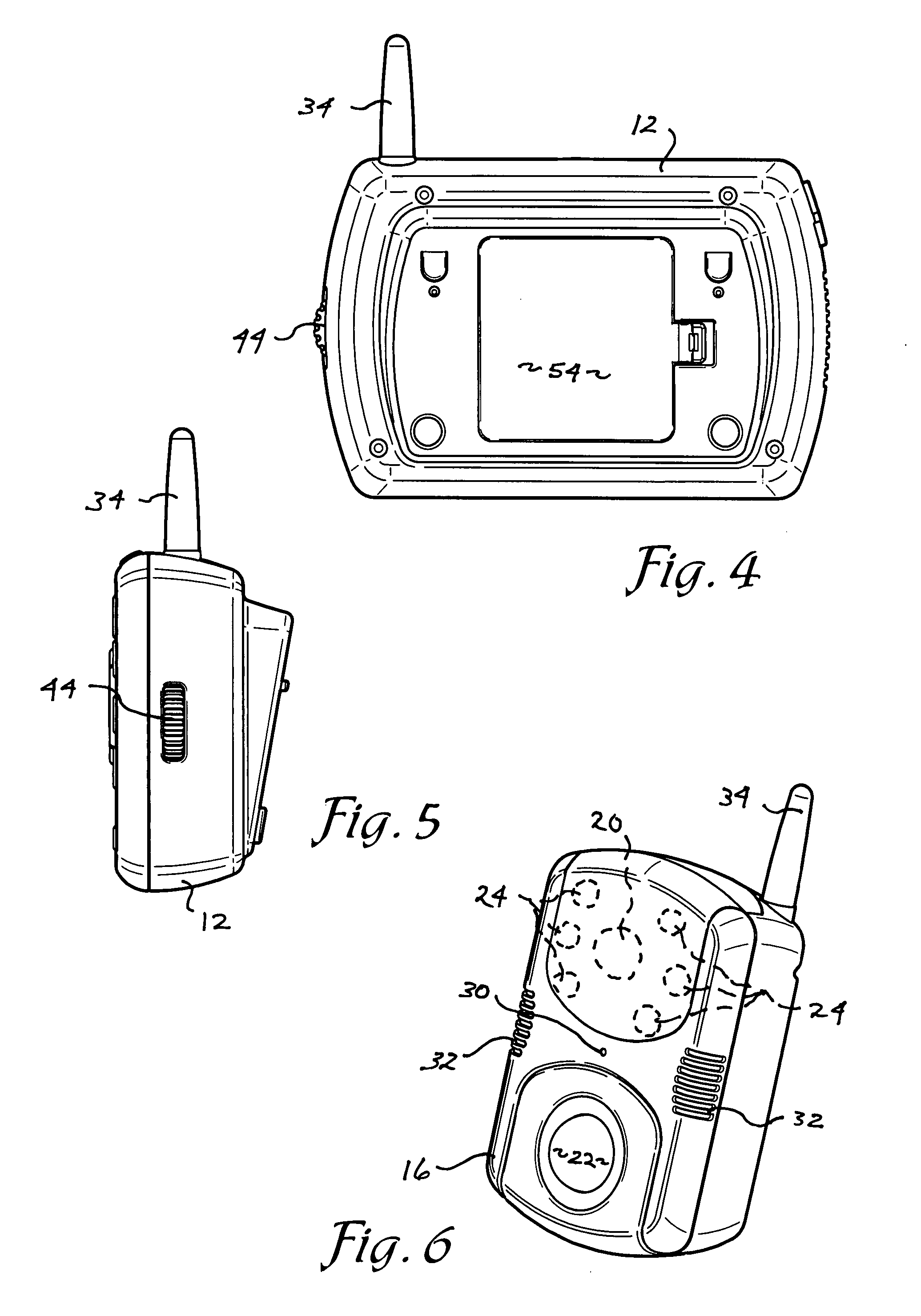
[0026] Referring now to FIG. 1 the present invention of the digital video surveillance system 10 is shown comprised of four different units as exemplified in FIGS. 1, 6, and 10. In summary the system is comprised of a control unit 12 (FIG. 1), one or more doorbell units 14 (FIG. 10), and accessory camera units of two different types that may be utilized with the control unit 12 of FIG. 1. The first type of accessory unit is a camera and intercom unit 16 as...


PUM


Abstract

A surveillance system is provided having a base unit for receiving digital video and audio transmissions from accessory units equipped with a camera having pan and tilt functions, a motion sensor, an intercom, infrared sensors and a doorbell button for contacting the interior of the dwelling a recording feature is provided to both automatically and on demand record video and audio transmissions received by the base unit from the accessory units.

Description

CROSS REFERENCE TO RELATED APPLICATION [0001] This application claims priority under 35 U.S.C. 119(e) and 37 C.F.R. 1.78(a)(4) based upon copending U.S. Provisional Application Ser. No. 60 / 838,530 for Digital Video Surveillance System filed Aug. 11, 2006 and which is incorporated herein by reference.FIELD OF THE INVENTION [0002] The present invention comprises a digital video surveillance system which may be used in residential or office applications to provide the observation of individuals appearing at an entrance of the premises. The present invention further provides the ability to link multiple accessory cameras with the control unit for surveillance of alternate locations on the exterior of the premises or within the premises. BACKGROUND OF THE INVENTION [0003] The need for home security has become an increasing concern in the United States and elsewhere. The instances of undesirable individuals confronting home owners at the front door of the dwelling under a ruse or entering...

Claims


Application Information

Patent Timeline
IPC IPC(8): H04N7/18
CPCH04N7/181H04N7/186
Inventor LANG, STEVESISKIND, BARRY
Owner MARCHE DESIGNS
Learn More