
Three-dimensional cavity-formed part having a multilayered structure and process of its manufacture

a three-dimensional cavity and multi-layered technology, applied in the direction of seating furniture, stools, thin material handling, etc., can solve the problems of inability to introduce or arrange cavities, cumbersome and cost-intensive, difficult and costly in the prior art to outfit the molded piece with deformable,

Inactive Publication Date: 2008-02-14
SKS SITZKOMPONENTEN
View PDF3 Cites 8 Cited by
  • Summary
  • Abstract
  • Description
  • Claims
  • Application Information

AI Technical Summary

Problems solved by technology

However, in the prior art it is often not possible to introduce or arrange cavities, especially air-filled cavities that can contribute to improving the sitting comfort of seating furniture, between the particular layers of the molded piece, especially so that the cavities can also withstand load over rather long periods of time and be more or less airtight.
Furthermore, it is difficult and costly in the prior art to outfit the molded piece with deformable bodies, such as gel cushions or foam plastic, inserted or arranged between the layers to afford a type of cushion effect and further enhance the sitting comfort.
In this regard, it is necessary in the prior art to first produce said deformable bodies in a separate process—i.e., in addition to the production of the molded piece—which is cumbersome and cost-intensive, since numerous additional work steps and separate process equipment are required.
Moreover, it is hard to integrate the separately produced deformable bodies in the molded piece, since properly positioning the deformable body inside the molded piece and joining it permanently to the molded piece is often unsuccessful.
Furthermore, the prior art does not always ensure that a deformable body already produced in a separate process and introduced into the molded piece will retain its original form during final production of the molded piece, e.g., when laminating a cover or sealing layer onto it, since additional stresses and forces can arise during heating of a textile surface material, that may permanently deform the deformable body.
Moreover, the fact that the textile surface material is applied to the substrate material only after forming of the sheetlike substrate and after outfitting the molded piece with the deformable bodies is disadvantageous since it makes gluing difficult; in particular, it is often not possible to connect the entire surface of the textile surface material to the formed material and the deformable body: in particular, in the region of intense forming, e.g., sharp bends, indentations or bulges or the like, there is an intensive stretching or compression of the textile surface material that can often lead to a detachment or delamination of the fabric.
Furthermore, when a textile surface material is applied afterwards to the already formed material, which can have a deformable body in addition, an unwanted formation of wrinkles often occurs.
A further drawback of this method is that a nonuniform tensile stressing of the textile surface material may result from the subsequent attachment of the textile surface material to the three-dimensional structure, which can lead to a nonuniform surface pattern and also an unwanted permanent deformation of the deformable body.
Finally, the large and nonuniform restoring forces resulting from subsequent, sometimes nonuniform “shrinking” of the textile surface material on the substrate structure can lead to a subsequent deformation of the molded piece.

Method used


Image

  • Three-dimensional cavity-formed part having a multilayered structure and process of its manufacture
  • Three-dimensional cavity-formed part having a multilayered structure and process of its manufacture
  • Three-dimensional cavity-formed part having a multilayered structure and process of its manufacture

Examples


Embodiment Construction

[0030]For the purposes of promoting an understanding of the disclosure, reference will now be made to the embodiments illustrated in the drawings and specific language will be used to describe the same. It will nevertheless be understood that no limitation of the scope of the disclosure is thereby intended, such alterations and further modifications in the illustrated device and its use, and such further applications of the principles of the disclosure as illustrated therein being contemplated as would normally occur to one skilled in the art to which the disclosure relates.

[0031]In the figures, the same reference numbers are used for the same or similar parts, and corresponding properties and advantages are achieved even if a repeated description is omitted for reasons of simplification.

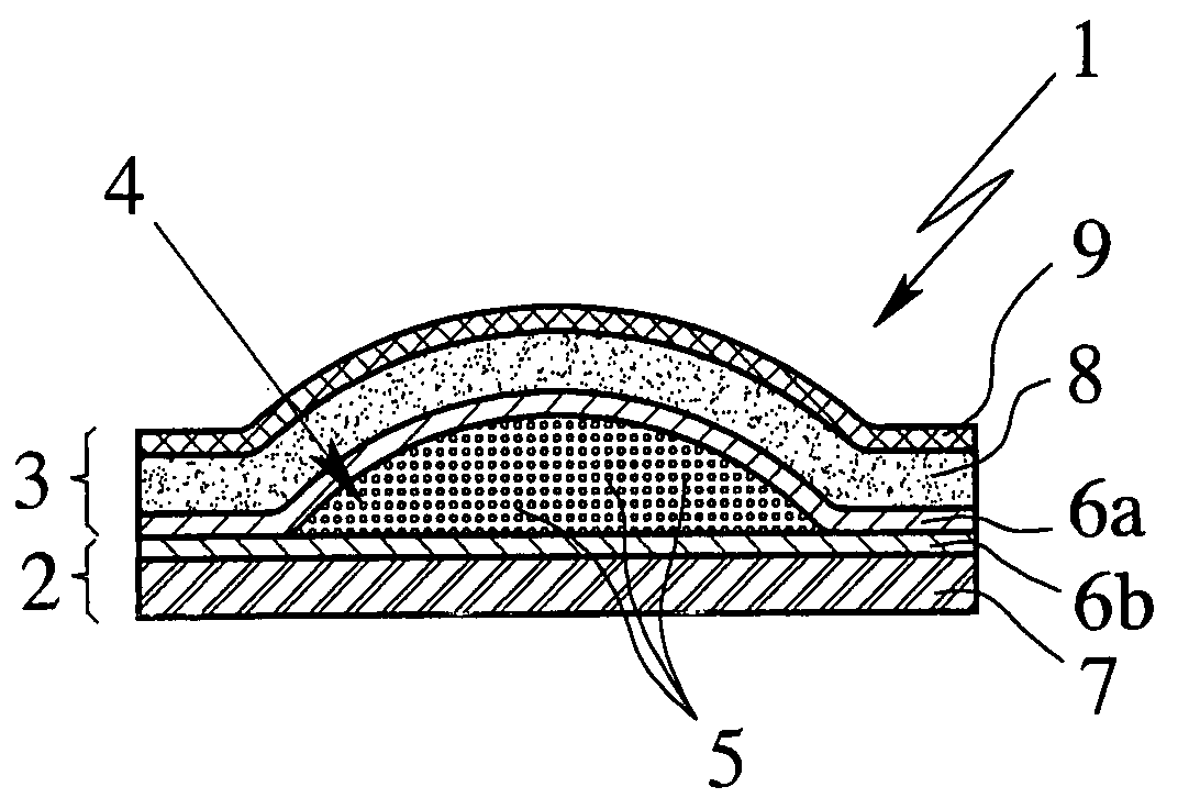
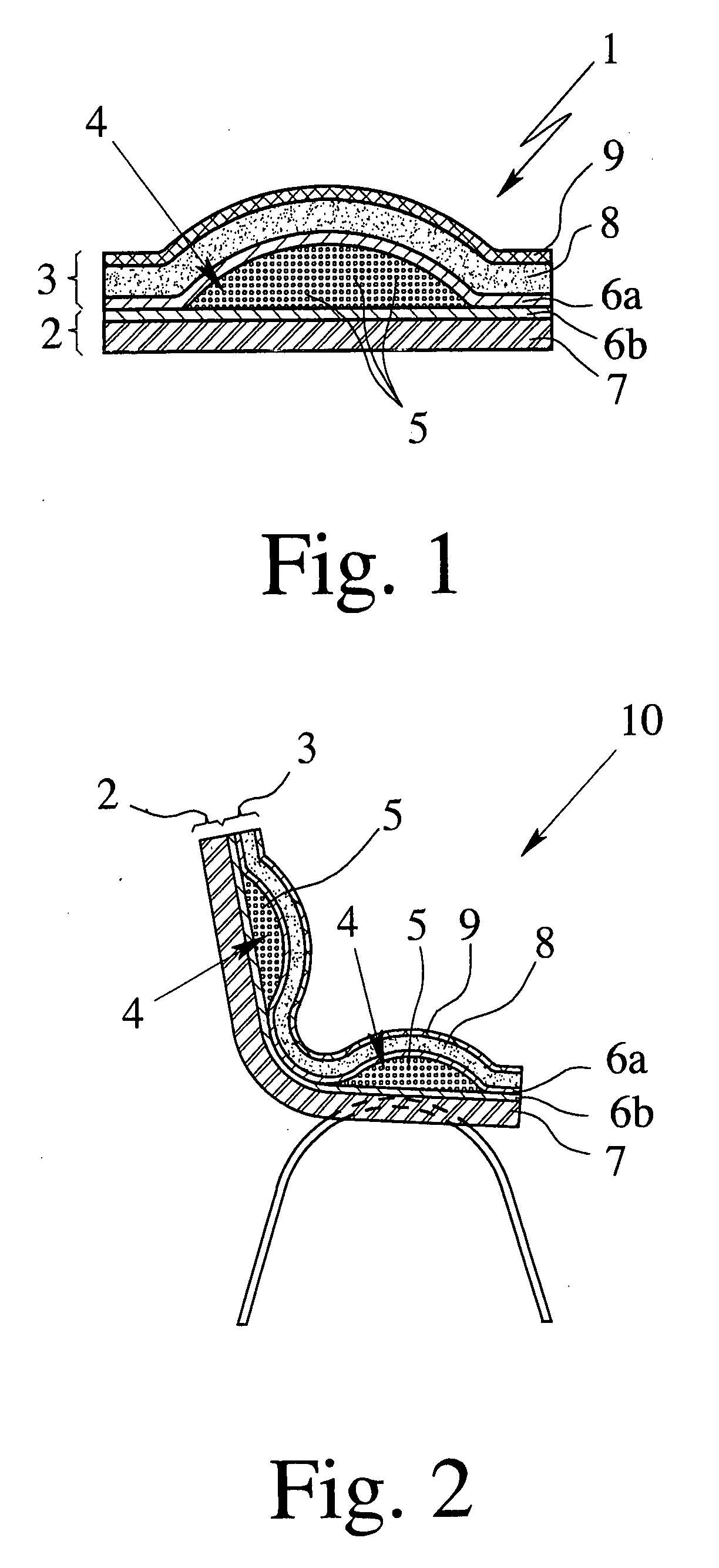
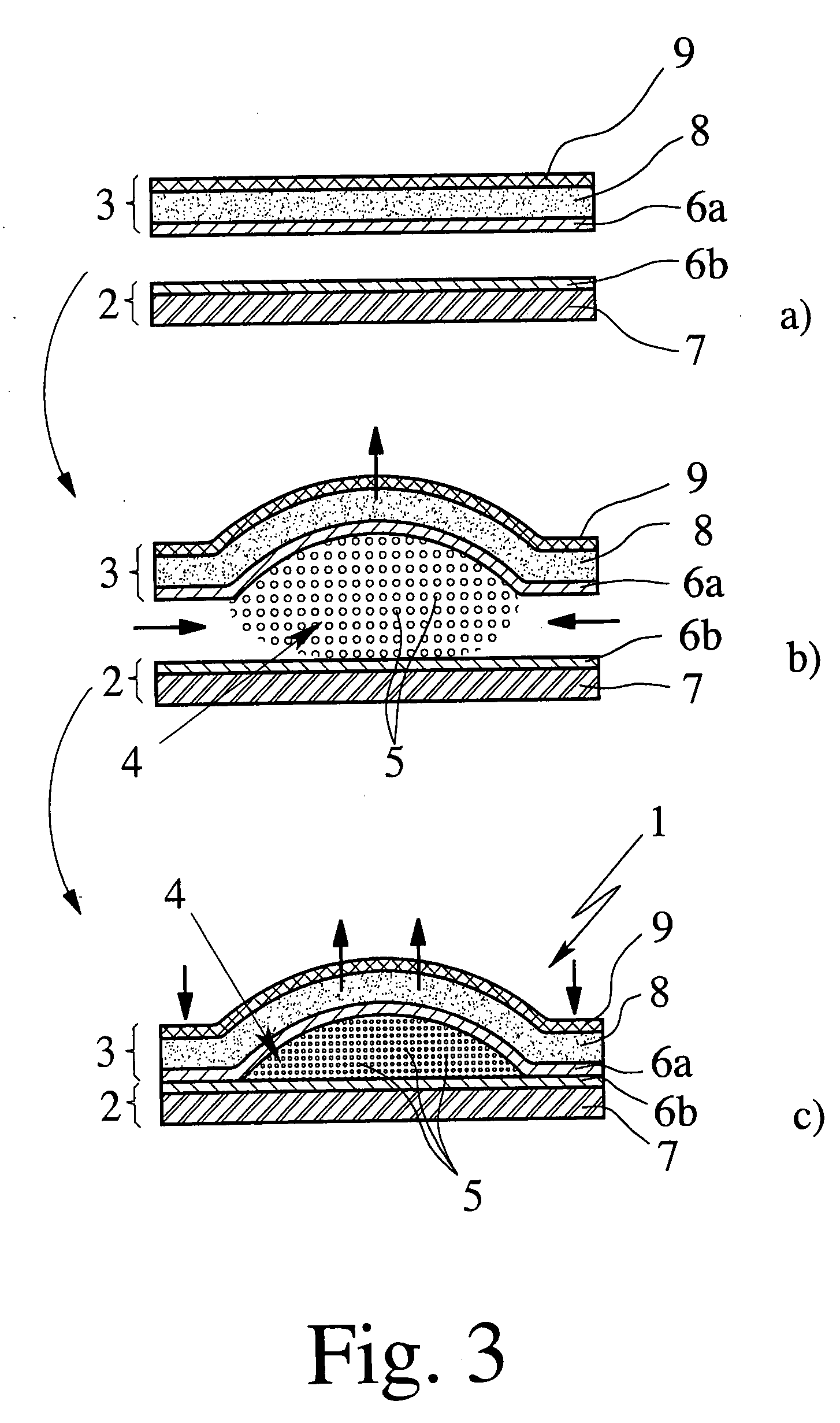
[0032]FIG. 1 shows an invented three-dimensional hollow molded piece 1 with multilayer construction, which is suitable in particular for the production of furnishings, especially furniture, preferab...


PUM

PropertyMeasurementUnit
thicknessaaaaaaaaaa
yield stressaaaaaaaaaa

Abstract

The invention concerns a three-dimensional hollow molded piece having a multilayered construction, with a cavity formed by a substrate material and a cover material. The cavity is arranged between the substrate material and the cover material and filled with a filling medium. The hollow molded piece has in relation to the substrate material and the cover material a filmlike layer at least essentially impermeable to the filling medium, which is especially suitable for use in the furniture industry, especially for the manufacture of seating furniture.

Description

CROSS REFERENCES TO RELATED APPLICATIONS[0001]This application claims priority to German Patent Application No. DE 10 2006 037 870.9, filed Aug. 11, 2006, and also claims priority to German Patent Application No. DE 10 2006 041 714.3, filed Sep. 6, 2006, entitled “THREE-DIMENSIONAL CAVITY-FORMED PART HAVING A MULTILAYERED STRUCTURE AND PROCESS OF ITS MANUFACTURE”. Both references are expressly incorporated by reference herein, in their entireties.BACKGROUND OF THE INVENTION[0002]The present invention concerns a three-dimensional hollow molded piece according to the disclosure, as well as its use, especially for the production of furnishings, especially furniture, preferably seating furniture, decorative elements, hollow conduits, automotive accessories and the like, as well as the furnishings of the aforesaid kind made in this way. Finally, the present invention concerns a method for production of such a hollow molded piece.[0003]In regard to the production of multilayered molded pi...

Claims


Application Information

Patent Timeline
Patent Type & Authority Applications(United States)
IPC IPC(8): B32B1/06
CPCA47C5/00A47C7/18Y10T428/233B32B7/02B32B1/06B32B1/00
Inventor SALZMANN, OLIVER
Owner SKS SITZKOMPONENTEN
Learn More