Variable Optical Arrays and Variable Manufacturing Methods

a manufacturing method and technology of lens array, applied in the field of lens array, can solve the problems of changing the characteristics of the lens, inability to produce arrays with very small lenses, and large number of lens elements

Inactive Publication Date: 2008-02-21
TEMEKU TECH
View PDF49 Cites 23 Cited by
  • Summary
  • Abstract
  • Description
  • Claims
  • Application Information

AI Technical Summary

Benefits of technology

[0012] The powerful practical impact of the present invention is that a great number of optical elements may be created in a small area (approximately 90,000 discrete lenses per square foot), and the lens curvature may be varied without necessarily having to change the tooling for the lens elements.

Problems solved by technology

Even if there had been such an effort, there is a difficulty in producing a large number of lens elements in the arrays, an inability to produce arrays with very small lenses, and the troubles associated with changing the characteristics of the lenses after an array-making tool has been fabricated.
Making such a tool is extremely expensive, extremely difficult, and not amenable to modification once it is made.

Method used


Image

  • Variable Optical Arrays and Variable Manufacturing Methods
  • Variable Optical Arrays and Variable Manufacturing Methods
  • Variable Optical Arrays and Variable Manufacturing Methods

Examples


first embodiment

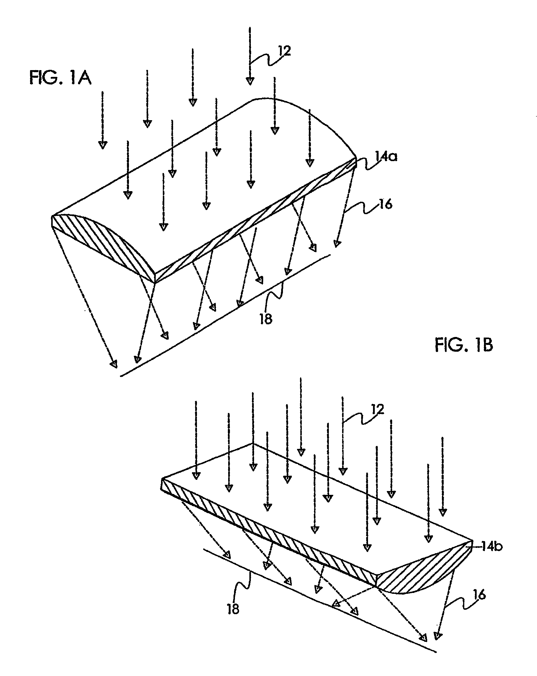
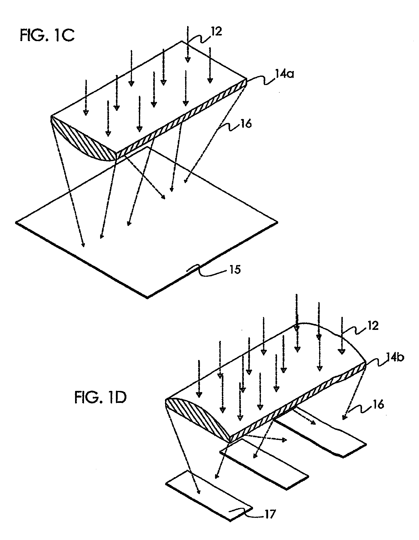
[0101] In FIG. 10, a tool 134 is created by making a series of longitudinal cuts to create thin walls 102 spaced at a distance D of preferably 1 mm. Tool 134 is shown with v-shaped longitudinal cuts, but can also have square cuts. Holes (not shown) or even grooves, may be placed along the bottom of the cuts to provide communication for a differential pressure V. A sheet of film 104, transparent or reflective, is placed over the walls 102. Then, differential pressure V is applied via the holes (not shown) between the walls 102 to pull the film 104, and a curved axial optic 110 is formed. It is very important to understand that there is no further polishing of the optic that is required in order to have an optical quality surface. Then, in a first embodiment, a polymer 112 may be poured behind the curved axial optic 110, and a permanent axial optic is created, having a light focusing ability as shown in FIG. 2A. A preferred polymer material may be obtained from Applied Poleramics, Inc...

second embodiment

[0102] In a second embodiment, a transparent tool 100 may be used with film 104. Here, the curved axial optic is continuously variable in curvature depending upon varying level of differential pressure. When a projected image is focused through the curved axial optic, the curvature of the optic may be changed by changing the level of differential pressure V, thereby yielding a variation in the focus of the image. This has very useful applications when the changing focus is coordinated with either a changing image or a changing viewer location.

[0103] In any preferred embodiment, any film 104 may be used such as acetate, polyethylene, polypropylene, polycarbonate, or acrylic where the thickness is preferably between 0.25 mils and 1 mil.

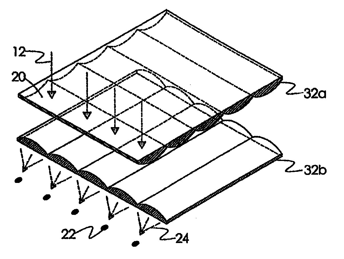
[0104] When two tools 100 are employed simultaneously, facing each other in a crossed relationship, then it is easily seen that a crossed optical array is created. Then, the space between the films 104 may be filled with a plastic (the term “plastic” i...


PUM


Abstract

The invention divides the lens focusing process into two or more surfaces that incorporate multiple curved axial optic elements on each surface. The axial optics may be manufactured by molding, machining, or by suspended film. If suspended film is used, then both sides of an optic may have a suspended film that is transparent. Alternatively, one side of the suspended film optic may use a reflective film.

Description

CROSS-REFERENCE TO RELATED APPLICATIONS [0001] This application is a continuation-in-part of U.S. application Ser. No. 10 / 993,423 titled “Variable Optical Arrays and Variable Manufacturing Methods” filed on Nov. 18, 2004, which claims the benefit of U.S. Provisional Application No. 60 / 523,076 titled “Optical Arrays That Can Be Easily Manufactured Over a Large Range of Sizes And Densities” filed on Nov. 18, 2003. The disclosures of both of the above applications are incorporated herein by reference in their entirety. [0002] This application is related to U.S. Provisional Application No. 60 / 523,006 titled “Reflective Multi-Image Surface” filed on Nov. 18, 2003, and further filed as a U.S. Non-Provisional Application filed on Nov. 18, 2004. This application is related to U.S. Provisional Application No. 60 / 536,861 titled “Spatially Multiplexed Image Projector” filed on Jan. 16, 2004. This application is related to a U.S. Provisional Application titled “Catadioptric Projection Screen” f...

Claims


Application Information

Patent Timeline
Patent Type & Authority Applications(United States)
IPC IPC(8): G03B21/60
CPCG03B21/60
Inventor POULSEN, PETER D.
Owner TEMEKU TECH
Why Eureka
Try Eureka