Monolithic integration of nonplanar solar cells

a solar cell and monolithic technology, applied in the field of solar cell assemblies, can solve the problems of shunting across the junction, reducing the efficiency of increasing the occurrence of pinholes and similar flaws in larger planar solar cells

Inactive Publication Date: 2008-02-28
SOLYNDRA
View PDF44 Cites 75 Cited by
  • Summary
  • Abstract
  • Description
  • Claims
  • Application Information

AI Technical Summary

Benefits of technology

[0014] In some embodiments, the plurality of photovoltaic cells comprise (i) a first terminal photovoltaic cell at the first end of the substrate, (ii) a second terminal photovoltaic cell at the second end of the substrate, and (iii) at least one intermediate photovoltaic cell between the first terminal photovoltaic cell and the second photovoltaic cell. The transparent conductive layer of each intermediate photovoltaic cell in the at least one intermediate photovoltaic cell is in serial electrical communication with the back-electrode of an adjacent photovoltaic cell in the plurality of photovoltaic cells. In some embodiments, the adjacent photovoltaic cell is the first terminal photovoltaic cell or the second terminal photovoltaic cell. In some embodiments, the adjacent photovoltaic cell is another intermediate photovoltaic cell. In some embodiments, the plurality of photovoltaic cells comprises three or more photovoltaic cells, ten or more photovoltaic cells, fifty or more photovoltaic cells, or one hundred or more photovoltaic cells.

Problems solved by technology

However, even when a TCO layer is present, a bus bar network 114 is typically needed in conventional solar cells to draw off current since the TCO has too much resistance to efficiently perform this function in larger solar cells.
Although such cells are highly efficient when they are smaller, larger planar solar cells have reduced efficiency because it is harder to make the semiconductor films that form the junction in such solar cells uniform.
Furthermore, the occurrence of pinholes and similar flaws increase in larger planar solar cells.
These features can cause shunts across the junction.

Method used


Image

  • Monolithic integration of nonplanar solar cells
  • Monolithic integration of nonplanar solar cells
  • Monolithic integration of nonplanar solar cells

Examples


Embodiment Construction

[0043] Disclosed herein are nonplanar solar cell units comprising a plurality of photovoltaic cells linearly arranged on a substrate in a monolithically integrated manner.

5.1 Basic Structure

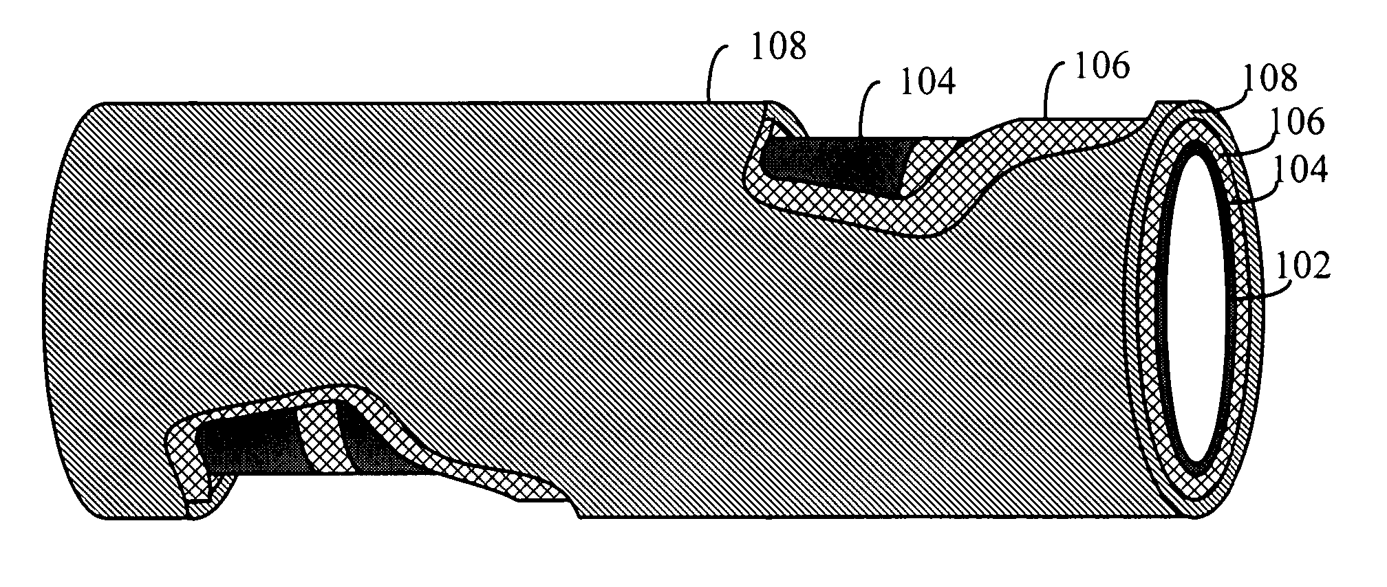
[0044]FIG. 7 illustrates the cross-sectional view of an exemplary embodiment of a photovoltaic cell 700. In some embodiments, a solar cell unit comprises a plurality of photovoltaic cells 700 linearly arranged on a nonplanar substrate in a monolithically integrated manner.

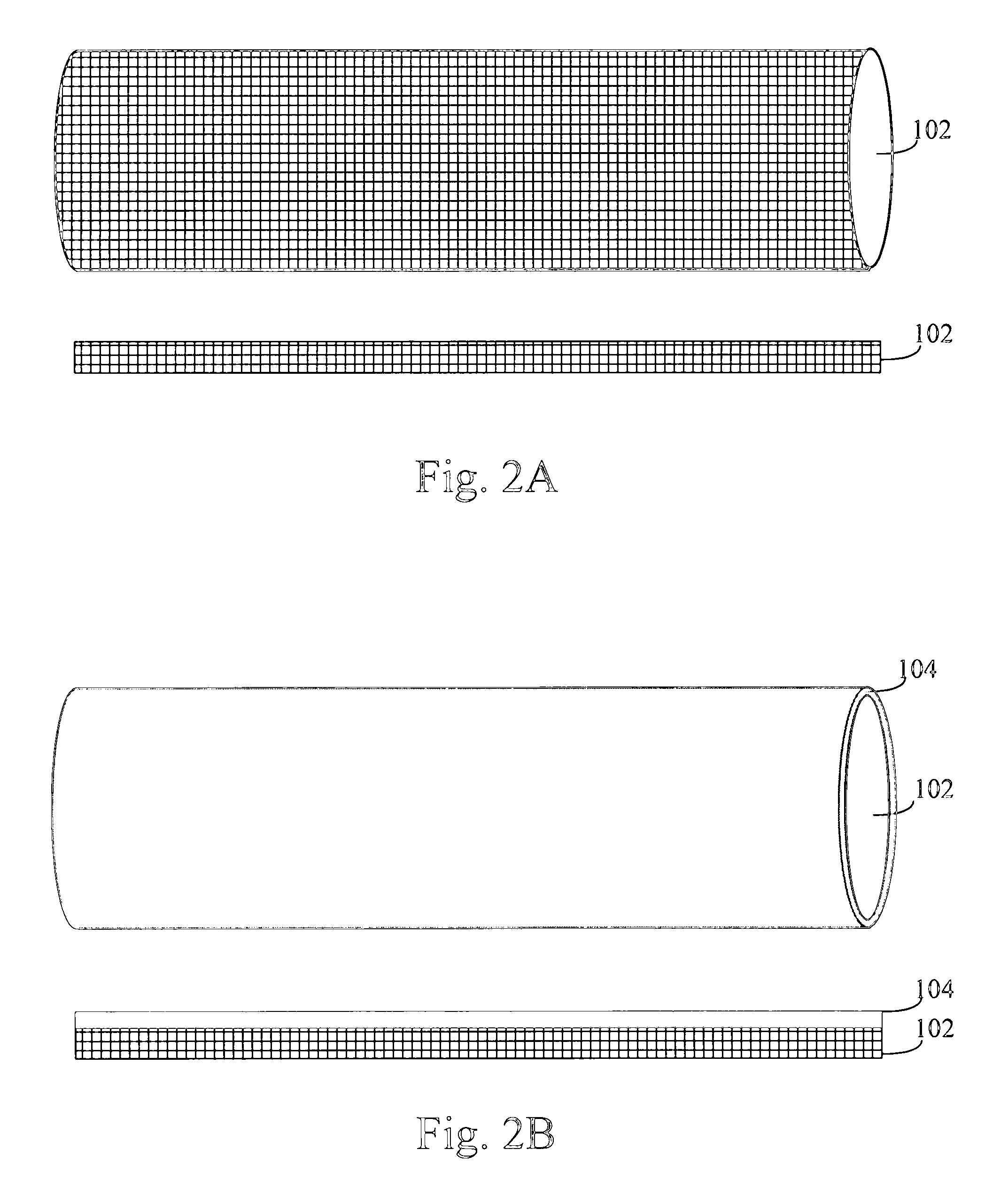
[0045] Substrate 102. A substrate 102 serves as a substrate for the solar cell unit. In some embodiments, all or a portion of the substrate 102 is a nonplanar closed form shape. For instance, in some embodiments, all or a portion of the substrate 102 is a rigid tube or a rigid solid rod. In some embodiments, all or a portion of the substrate 102 is any solid or hollowed cylindrical shape. In some embodiments, the substrate 102 is a rigid tube made out plastic metal or glass. In some embodiments, the overall outer shape of the...


PUM


Abstract

A solar cell unit is provided that has a substrate having a first end and a second end, where at least a portion of the substrate is rigid and nonplanar. The solar cell unit has a plurality of photovoltaic cells linearly arranged on the substrate, including a first and second photovoltaic cell. Each photovoltaic cell in the plurality of photovoltaic cells comprises a back-electrode circumferentially disposed on the substrate, a semiconductor junction layer circumferentially disposed on the back-electrode, and a transparent conductive layer circumferentially disposed on the semiconductor junction. The transparent conductive layer of the first photovoltaic cell in the plurality of photovoltaic cells is in serial electrical communication with the back-electrode of the second photovoltaic cell in the plurality of photovoltaic cells.

Description

CROSS REFERENCE TO RELATED APPLICATION [0001] This application is a continuation-in-part of U.S. patent application Ser. No. 11 / 378,835 entitled “Monolithic Integration of Cylindrical Solar Cells,” filed on Mar. 18, 2006, which is hereby incorporated by reference herein its entirety.1. FIELD [0002] This application relates to solar cell assemblies for converting solar energy into electrical energy and more particularly to improved solar cell assemblies. 2. BACKGROUND [0003] Solar cells are typically fabricated as separate physical entities with light gathering surface areas on the order of 4-6 cm2 or larger. For this reason, it is standard practice for power generating applications to mount the cells in a flat array on a supporting substrate or panel so that their light gathering surfaces provide an approximation of a single large light gathering surface. Also, since each cell itself generates only a small amount of power, the required voltage and / or current is realized by interconn...

Claims


Application Information

Patent Timeline
Patent Type & Authority Applications(United States)
IPC IPC(8): H01L31/042
CPCH01L31/035281H01L31/05H01L31/055Y02E10/52H02S40/44H01L31/0547H01L31/0475H01L31/046Y02E10/60H01L31/0463H01L31/0465
Inventor BULLER, BENYAMINBECK, MARKUS E.
Owner SOLYNDRA
Why Eureka
Try Eureka