Display device

a display device and display element technology, applied in the field of display devices, can solve the problems of easy damage to display elements using glass substrates, difficulty in moving or carrying display devices, and increased weight of devices with an increase in the size of the display devi

Inactive Publication Date: 2008-02-28
UDC IRELAND
View PDF6 Cites 129 Cited by
  • Summary
  • Abstract
  • Description
  • Claims
  • Application Information

AI Technical Summary

Problems solved by technology

However, since the display devices were formed on nonflexible substrates such as a glass or the like, it was difficult to move or carry the display devices by decreasing thereof.
Further, the display elements using a glass substrate ar...

Method used


Image

  • Display device
  • Display device
  • Display device

Examples


Embodiment Construction

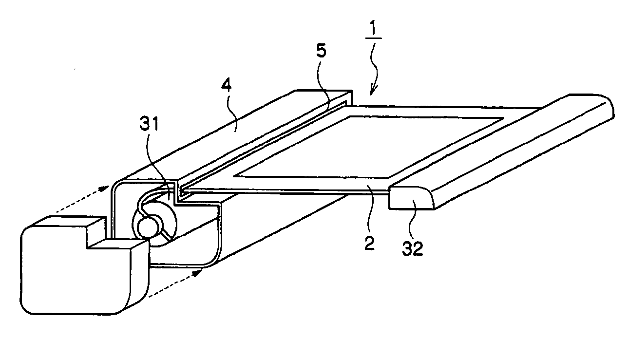
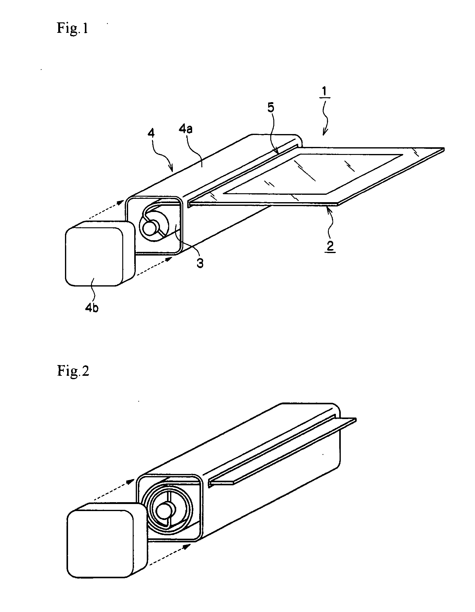
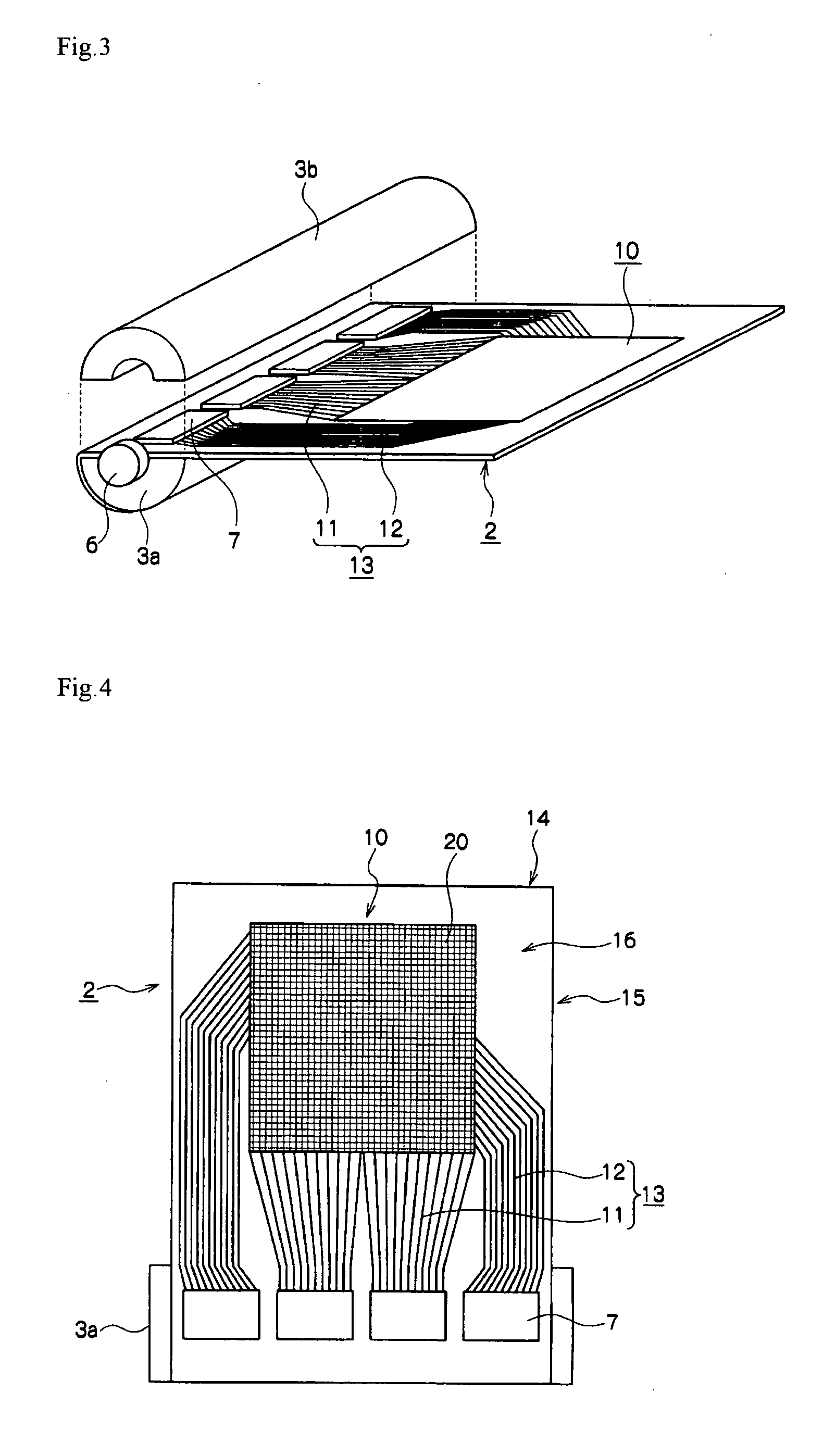
[0028]It has been found that a new problem occurs, which did not occur in a display element on a glass substrate, in that a display element using a flexible substrate is damaged due to a bending stress applied by housing by rolling and drawing out. In particular, there are problems in that a stripe electrode extending in a rolling direction of the display element is easily damaged due to a large bending stress and the display element becomes unable to display an image due to repetition of housing by rolling and drawing out.

[0029]An object of the present invention is to provide a display device in which a display device is not damaged even when repetition of housing by rolling and drawing out is performed. Further, the object of the invention is to thereby easily provide a display device in which an increase in size of a screen is compatible with a decrease in size and a decrease in weight of the display device, and to provide a display device resistant to an impact such as a drop.

[0...


PUM


Abstract

A display device including a display unit and a circuit unit for driving the display unit, in which the display unit includes a flexible substrate and can be housed by rolling and drawn out in a predetermined direction, one electrode is a metal electrode, and the other electrode is a stripe-shaped electrode comprising a metal oxide, and a long side of the stripe is disposed perpendicular to a rolling direction of the display device.

Description

CROSS-REFERENCE TO RELATED APPLICATION[0001]This application claims priority under 35 USC 119 from Japanese Patent Application No. 2006-228025, the disclosure of which is incorporated by reference herein.BACKGROUND OF THE INVENTION[0002]1. Field of the Invention[0003]The present invention relates to a display device in which a display unit can be housed by rolling and drawn out.[0004]2. Description of the Related Art[0005]Conventionary, cathode ray tubes were widely used in display devices of data processors, televisions or like. Thereafter, plasma display elements, liquid crystal display elements, and electroluminescence elements (hereinafter, referred to as an EL element), for example, have been used as flat panel display devices for the purpose of saving space. However, since the display devices were formed on nonflexible substrates such as a glass or the like, it was difficult to move or carry the display devices by decreasing thereof. Further, the display elements using a glass...

Claims


Application Information

Patent Timeline
IPC IPC(8): G06F3/038
CPCG06F1/1615G06F1/1683G06F1/1652G06F1/1637
Inventor HASEGAWA, KAZUHIRO
Owner UDC IRELAND
Why Eureka
Try Eureka