Spinal alignment system and related methods

a spine alignment and spine technology, applied in the field of spine alignment system, can solve problems such as lateral deviation of the spine, scoliosis, and failure of the entire system

Inactive Publication Date: 2008-03-13
NUVASIVE
View PDF13 Cites 122 Cited by
  • Summary
  • Abstract
  • Description
  • Claims
  • Application Information

AI Technical Summary

Benefits of technology

[0016] Various coupling mechanisms are disclosed to provide multiple degrees of freedom prior to fixation. In the preferred embodiment, the mechanism includes a fixed or adjustable-length rod having ball-shaped ends coupled to a vertebral connector providing multiple degrees of freedom before being locked into position once a desired orientation is achieved.

Problems solved by technology

A common problem is lateral deviation of the spine, commonly termed scoliosis.
The Harrington instrumentation system has been used successfully for some time, but because the distraction rod is fixed to the spine in only two places, failure at either end causes the entire system to fail.
Another deficiency with existing mechanisms and approaches is that the single rod used to correct the defects must be contoured to fit various attachment sites.
In patients having compound spinal deformity, this may be extremely difficult.
A further problem is that the contoured rod frequently limits further correction of certain types of deformities.
That is, once the rod is in position, further correction of the deformity is difficult, since existing systems tend to limit incremental alignment procedures.
Sublaminar fixation utilizing current devices has two primary weaknesses, however.
Second, the thin wires can cut in some instances right through the lamina.
However, the plates are stacked on top of one another at each attachment site, resulting in an overall structure that tends to be quite thick.
Additionally, the teachings of the '759 patent do not allow for easy correction or preservation of sagittal alignment.

Method used


Image

  • Spinal alignment system and related methods
  • Spinal alignment system and related methods
  • Spinal alignment system and related methods

Examples


Embodiment Construction

[0139] Illustrative embodiments of the invention are described below. In the interest of clarity, not all features of an actual implementation are described in this specification. It will of course be appreciated that in the development of any such actual embodiment, numerous implementation-specific decisions must be made to achieve the developers' specific goals, such as compliance with system-related and business-related constraints, which will vary from one implementation to another. Moreover, it will be appreciated that such a development effort might be complex and time-consuming, but would nevertheless be a routine undertaking for those of ordinary skill in the art having the benefit of this disclosure. The spinal alignment apparatus and related methods disclosed herein boast a variety of inventive features and components that warrant patent protection, both individually and in combination.

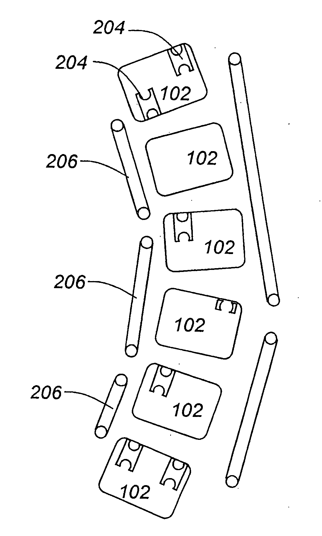
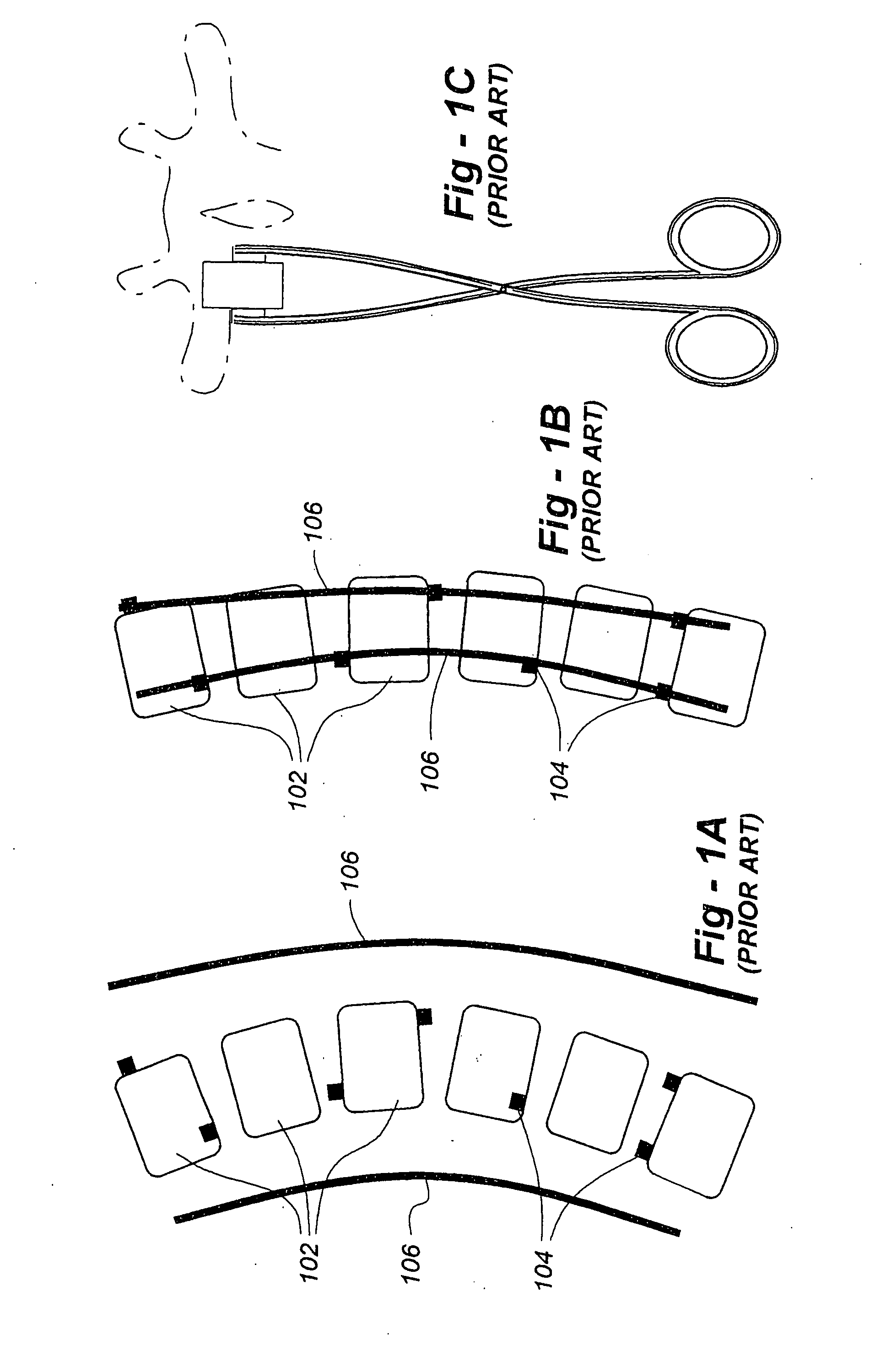
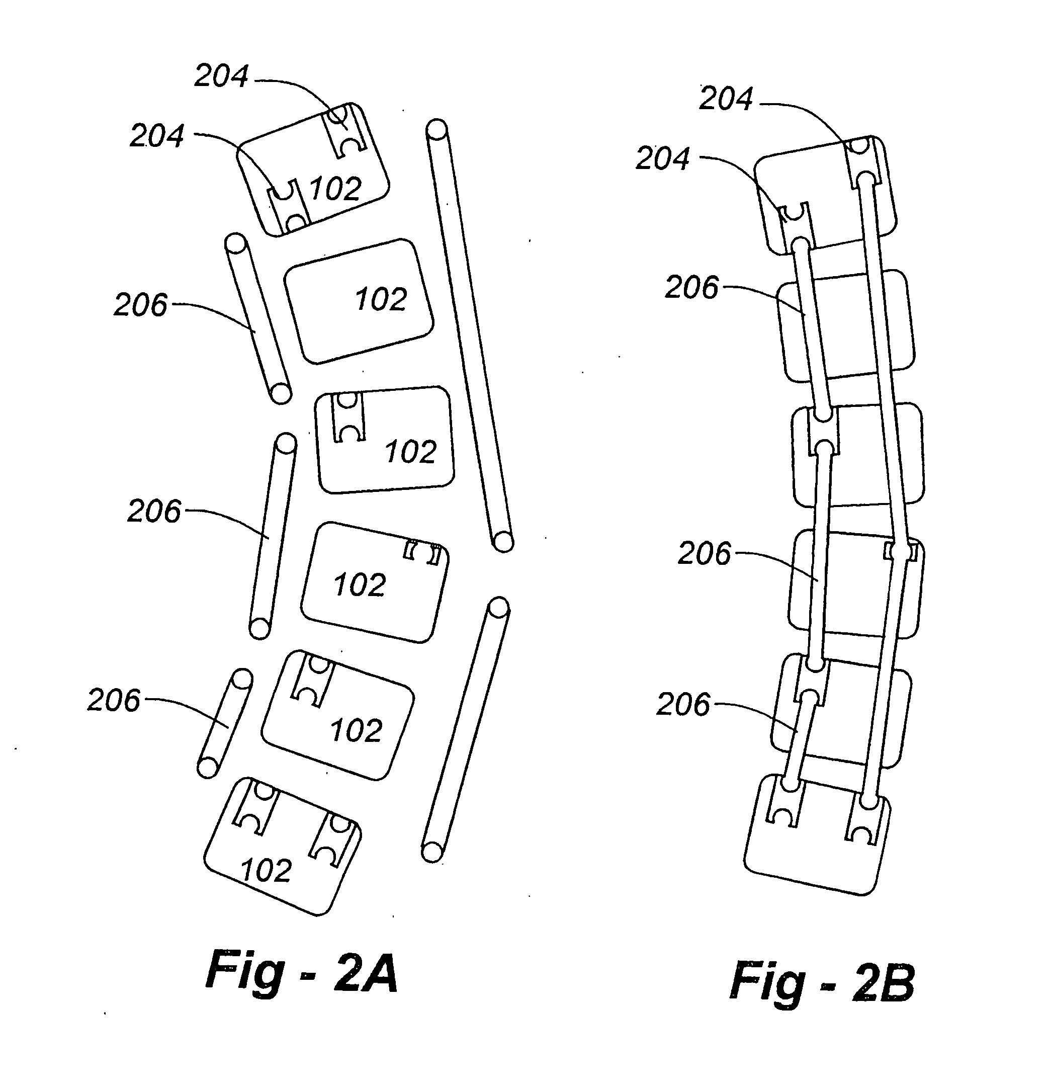
[0140]FIGS. 1A through 1C present simplified representations regarding the way in which...


PUM


Abstract

A spinal alignment system is disclosed and includes vertebral connectors, elongated elements that link the vertebral connectors, and fasteners that lock the elongated elements in position. An elongated element has at least one shaped end that is received by a coupling member of the connector. The shaped end permits the elongated element to be angularly moveable with respect to the coupling member until locked in place with a fastener received in the coupling member. The elongated element also preferably includes a length adjustment mechanism, such as a telescoping or threaded section to provide a desired length in conjunction with a desired degree of alignment. Various coupling mechanisms are disclosed to provide multiple degrees of freedom prior to fixation.

Description

CROSS REFERENCES TO RELATED APPLICATIONS [0001] The present application claims priority under 35 U.S.C. §120 from the commonly owned and co-pending U.S. patent application Ser. No. 10 / 894,533, filed on Jul. 19, 2004, which itself claims priority under 35 U.S.C. §120 from U.S. patent application Ser. No. 10 / 105,971, filed on Mar. 25, 2002, now issued as U.S. Pat. No. 6,802,844, the complete disclosures of which are hereby incorporated herein by reference in their entireties for all purposes. Additionally, the present application claims benefit under 35 U.S.C. §119(e) from U.S. Provisional Application Ser. No. 60 / 278,910, filed on Mar. 26, 2001, the entire contents of which are hereby expressly incorporated by reference into this disclosure as if set forth fully herein.BACKGROUND OF THE INVENTION [0002] I. Field of the Invention [0003] This invention relates generally to instrumentation, tools and techniques associated with spinal fixation and, in particular, to apparatus and methods ...

Claims


Application Information

Patent Timeline
Patent Type & Authority Applications(United States)
IPC IPC(8): A61B17/70A61B17/58A61B17/88A61F2/44
CPCA61B17/7005A61B17/701A61B17/7011A61B17/7014A61B2017/7073A61B17/7025A61B17/705A61B17/7052A61B17/7053A61B17/7022
Inventor FERREE, BRETT A.
Owner NUVASIVE
Why Eureka
Try Eureka