Camera integrated firearm system and method

a firearm system and integrated technology, applied in the field of integrated firearm systems and methods, can solve the problems of unreliable, conflicting witnesses, and often unreliable, and achieve the effect of maintaining weapon accuracy, reliability, and safety

Inactive Publication Date: 2008-03-20
FIDLOW HAL
View PDF17 Cites 23 Cited by
  • Summary
  • Abstract
  • Description
  • Claims
  • Application Information

AI Technical Summary

Benefits of technology

[0006]It is still another object of the present invention to provide a camera integrated firearm system and method which does not alter the outward configuration or operation of the firearm in any manner.
[0007]It is further object of the present invention to provide a camera integrated firearm system and method which maintains the weapon's accuracy, safety, and reliability.
[0008]It is still a further object of the present invention to provide a camera integrated firearm system and method which allows the use of existing technology to modify existing handguns and other firearms by replacing the original recoil spring guide assembly of the weapon with the system of the present invention.

Problems solved by technology

However, witness observations, after the fact, are often conflicting and unreliable.

Method used


Image

  • Camera integrated firearm system and method
  • Camera integrated firearm system and method
  • Camera integrated firearm system and method

Examples


Embodiment Construction

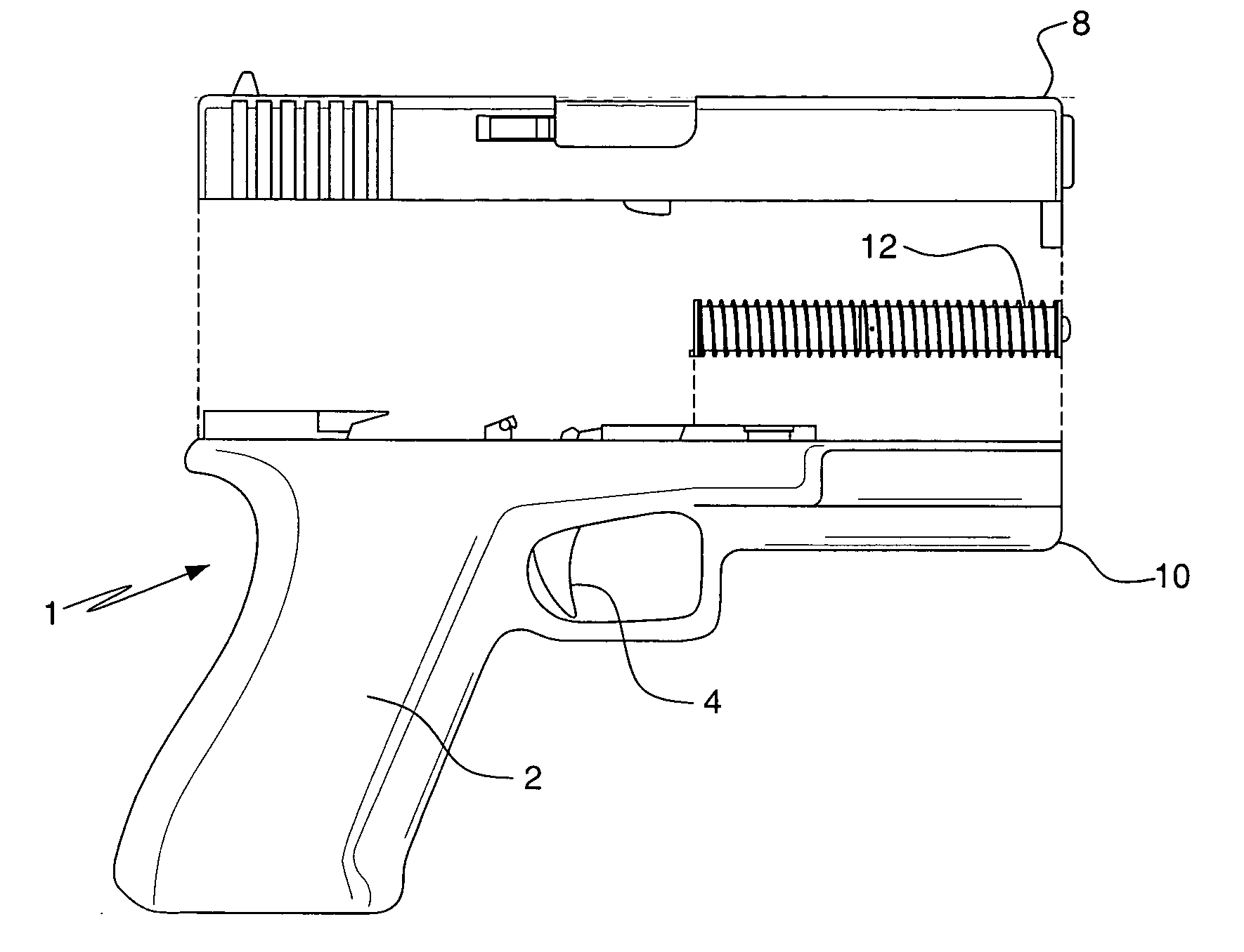
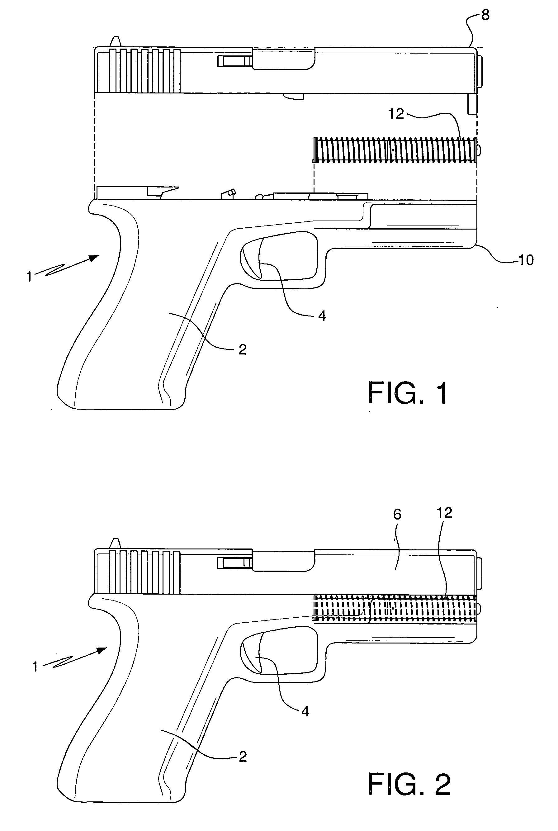
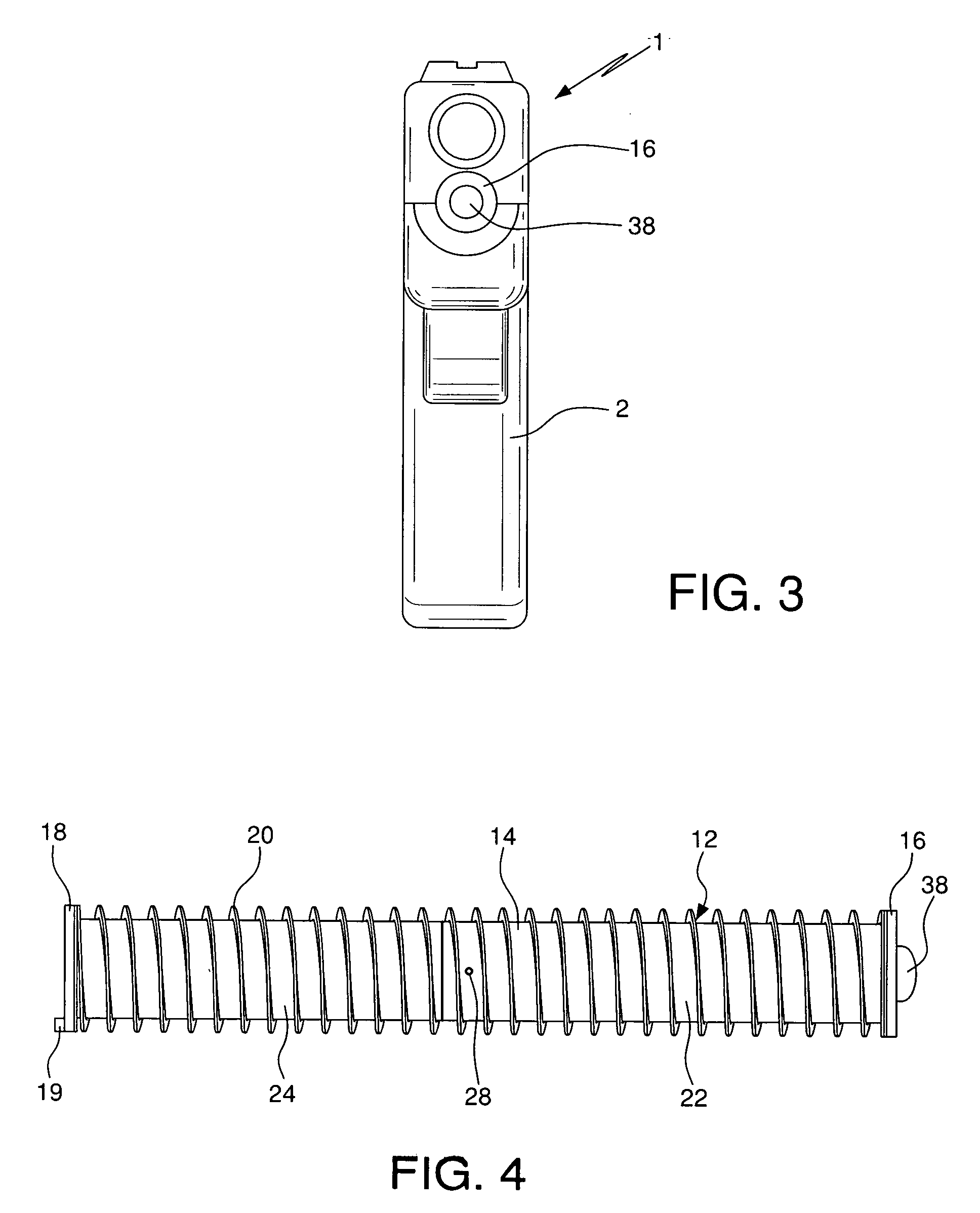
[0021]Handgun 1 comprises gun body 2 having trigger 4 and gun barrel or muzzle 6, with upper half 8 and lower half 10. Recoil spring guide camera assembly 12 is configured to replace the standard recoil spring guide in lower half 10 of muzzle 6 of the gun. Assembly 12 comprises outer casing or housing 14. Casing 14 is optimally made of corrosion resistant steel or similar metal. Recoil spring 20 circumscribes housing 14. Recoil spring retention walls 16 and 18 of assembly 12 are located at the ends of casing 14. Raised notch 19 is provided on the back of rear wall 18. The notch indexes the slot in the receiver (not shown) in lower portion 10 of gun 1, in order to maintain orientation of assembly 12.

[0022]Casing 14 is comprised of front section 22 and rear section 24. Sections 22 and 24 are threadably connected at 26 and secured with barrel locking screws 28. An O-ring spacer 29, provides a secure seal between sections 22 and 24.

[0023]Rear section 24 comprises open space 30 in which ...


PUM


Abstract

A camera integrated firearm system replaces the original recoil spring and guide assembly of a firearm with a casing which includes a camera, a gunshot impact sensing and switching module, an image memory module, and output data ports. When the weapon is discharged, the sensing and switching module senses this discharge and immediately turns on the camera. The camera, utilizing ambient light plus the light generated by muzzle flash, i.e. the jet of fire exiting the barrel at the instant the bullet exits the weapon, takes and saves, in memory, a closely spaced sequential stream of digital photographs or, alternatively, video recordings. Using the data outputs, the images can then be downloaded for viewing.

Description

RELATED APPLICATION[0001]Provisional application No. 60 / 844,934, filed on Sep. 5, 2006.BACKGROUND OF THE INVENTION[0002]The use of firearms by local, state, and federal law enforcement personnel, as well as the military and private security sectors, presents a variety of situations in which the very circumstances surrounding this usage becomes an issue. For instance, oftentimes there are questions as to whether the discharge of a weapon was necessary, what events dictated the firing of a weapon, or who was actually present on the scene and what those individuals may have been doing at the time a weapon was fired. Recounts and recreations of circumstances surrounding the use of firearms is critical to subsequent investigations. However, witness observations, after the fact, are often conflicting and unreliable. Inquiries would be well served if images of the actual incidents which are the subjects of investigation could be viewed by the finder of fact. As a result, the contemporaneou...

Claims


Application Information

Patent Timeline
Patent Type & Authority Applications(United States)
IPC IPC(8): F41G11/00
CPCF41A17/06
Inventor FIDLOW, HAL
Owner FIDLOW HAL
Why Eureka
Try Eureka