Eureka AIR delivers breakthrough ideas for toughest innovation challenges, trusted by R&D personnel around the world.

Bat used for baseball or softball

Inactive Publication Date: 2008-03-20
NIPPON SHAFT
View PDF24 Cites 45 Cited by
  • Summary
  • Abstract
  • Description
  • Claims
  • Application Information

AI Technical Summary

Problems solved by technology

In the case where this process is not carried out, the strength of the processed part decreases and damage etc occurs because durability is extremely inferior.
However, heat treatment of a double manufactured part is difficult to control and it is difficult to secure a sufficient level of strength and durability.
In particular, in the case of using a tube for the outer tube or inner tube of a different material to the bat body, which is of titanium or titanium alloy which excels in rebound force, with the aim of securing flight distance, controlling this heat treatment is extremely difficult.
Because, when the material of the outer tube or inner tube is different to that of the bat body, because each material's melting point is different, control of the heat treatment temperature and time becomes complex.
Therefore, by the construction of a conventional double layer bat, a bat for use in baseball or softball which excels in durability and rebound force, absorbs the ball transformation energy and extends flight distance has not been proposed.
However, because the urethane layers deteriorate as time passes, compared to a metal bat there is a problem whereby durability, unfortunately, is inferior.

Method used


Image

  • Bat used for baseball or softball
  • Bat used for baseball or softball
  • Bat used for baseball or softball

Examples


embodiment one

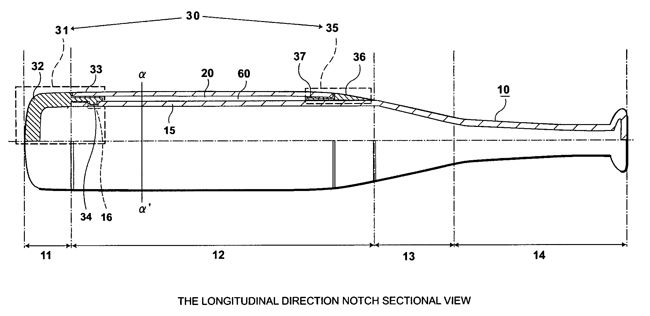
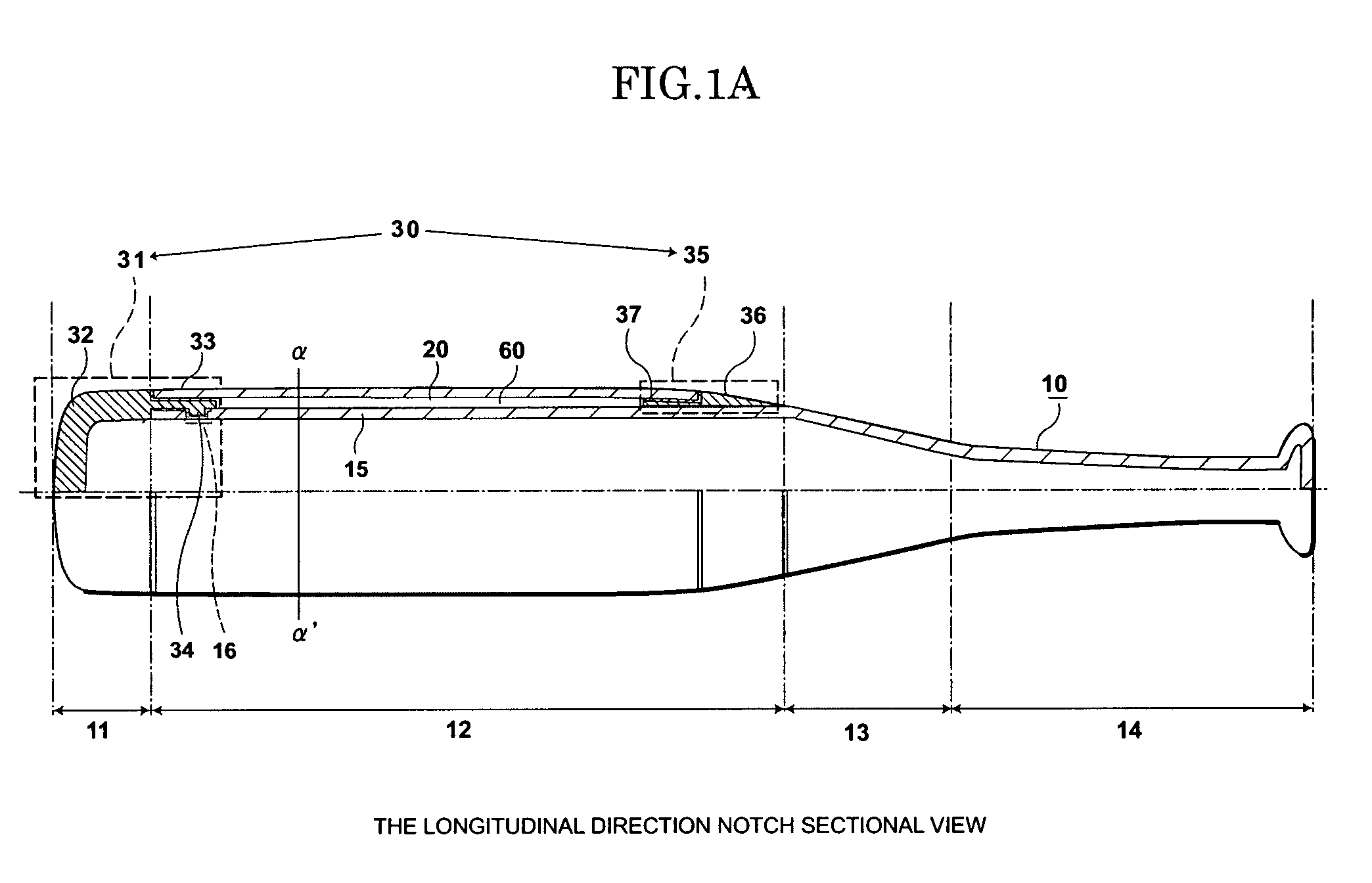
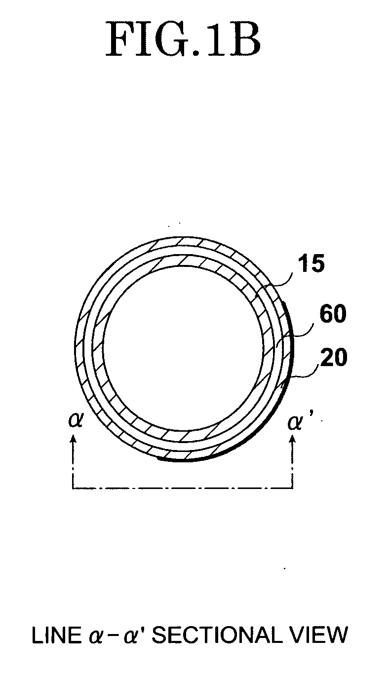
[0025] The bat used for baseball or softball relating to the first embodiment of this invention will be explained based on the drawings. FIG. 1 is a notch cross sectional view in a longitudinal direction and a cross sectional view across the width of a line α-α′. Further, in the embodiment, an example of a bat used for baseball or softball of this invention is shown and the bat used for baseball or softball of this invention is not limited to these embodiments.

[0026] In FIG. 1, the bat used for baseball or softball relating to the first embodiment of this invention comprises a bat body 10 which has a tip part 11, a first tube 15, a taper part 13 and a grip part 14, and a second tube 20 which is placed and latched on the outer circumference of the first tube 15 of the bat body, and a fixing component 20 which consists of a first fixing component 31 and a second fixing component 35. Further, in embodiment one of the present invention, the second tube 20 may be called outer tube 20.

[...

embodiment two

[0069] In the bat used for baseball or softball relating to embodiment one of this invention a second tube and the bat body are formed separately and because they are formed as one unit after each has been heat treated it is possible to form the second tube with the same material as the bat body and it is possible to form it with a material which has excellent rebound characteristics which are different from the bat body. However, because the entire length of the second tube itself becomes almost the same as the entire length of the first tube of the bat body, in the case where the second tube is formed, for example, with titanium which has excellent rebound characteristics, it is difficult to avoid an increase in costs. According to embodiment two of this invention while suppressing an increase in costs as much as possible, it is possible to efficiently transmit bat energy to a ball, and a bat which is used for baseball or softball is proposed which has excellent rebound characteri...


PUM

PropertyMeasurementUnit
Lengthaaaaaaaaaa
Lengthaaaaaaaaaa
Diameteraaaaaaaaaa

Abstract

A bat used for baseball or softball includes a bat body including a grip part, a taper part and a first tube, a fixing component including a first fixing component and a second fixing component and a cylindrical second tube having two opened ends, the inner diameter of the cylindrical second tube being larger than the diameter of the first tube, the second tube being placed on the outer circumference of the first tube and being latched so that a gap is formed between the bat body and the second tube via the first fixing component and the second fixing component.

Description

CROSS REFERENCE TO RELATED APPLICATION [0001] This application is based upon and claims the benefit of priority from the prior Japanese Patent Applications No. 2006-206829, filed on Jul. 28, 2006; the entire contents of which are incorporated herein by reference. BACKGROUND OF THE INVENTION [0002] 1. Field of the Invention [0003] This invention relates to the improvement of the rebound properties of a bat used for baseball or softball. [0004] 2. Description of the Related Art [0005] In recent times, in order to expand the durability of a metal bat, as shown in Japanese Laid Open Patent H05-57042, attempts at doubling the exterior or interior (exterior tube is called outer tube and interior tube is called inner tube) of the metal bat body by further arranging a metal tube have been made. This is known as a two layered bat. This aims to improve the strength of the bat by latching together the outer or inner tube with the body of the bat with no gap by a process such as swaging. In add...

Claims


Application Information

Patent Timeline
IPC IPC(8): A63B59/06A63B59/58A63B102/18
CPCY10T29/49879A63B59/06A63B59/50A63B59/51A63B59/56A63B2102/18A63B2102/182
Inventor WATARI, MAKOTOYOSHIDA, KOJI
Owner NIPPON SHAFT
Why Eureka
Eureka Blog
Learn More