Resilient container

a container and container technology, applied in the field of resilient containers, can solve problems such as additional effor

Inactive Publication Date: 2008-03-27
VETO PRO PAC
View PDF0 Cites 34 Cited by
  • Summary
  • Abstract
  • Description
  • Claims
  • Application Information

AI Technical Summary

Problems solved by technology

The scattering causes additional effort because someone will have to walk several feet, bend over and retrieve the sections for stacking, storage, transport or consumption.

Method used


Image

  • Resilient container
  • Resilient container
  • Resilient container

Examples


Embodiment Construction

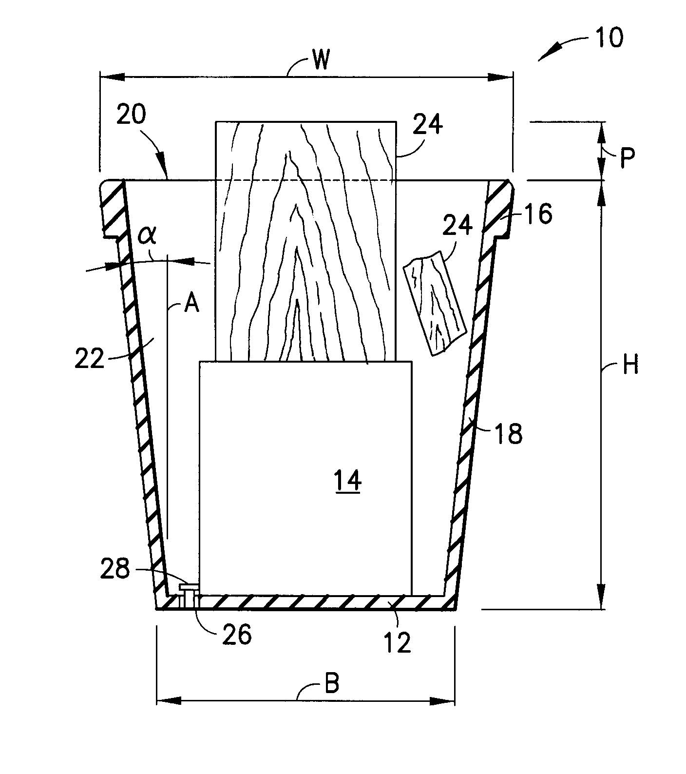
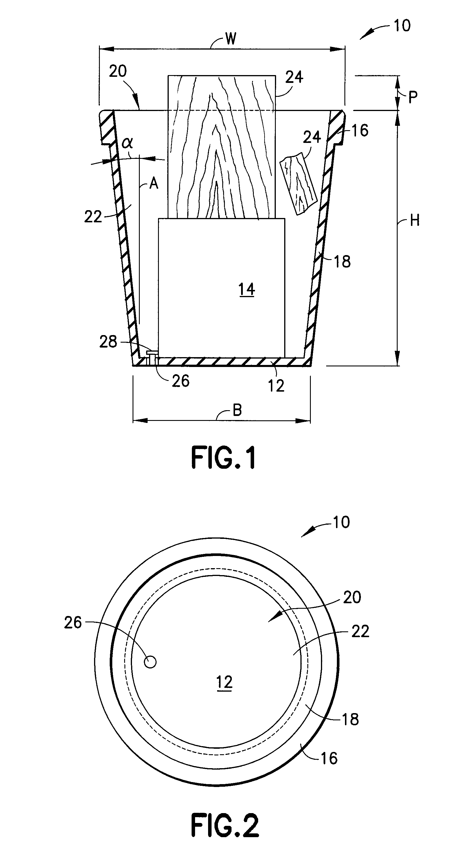
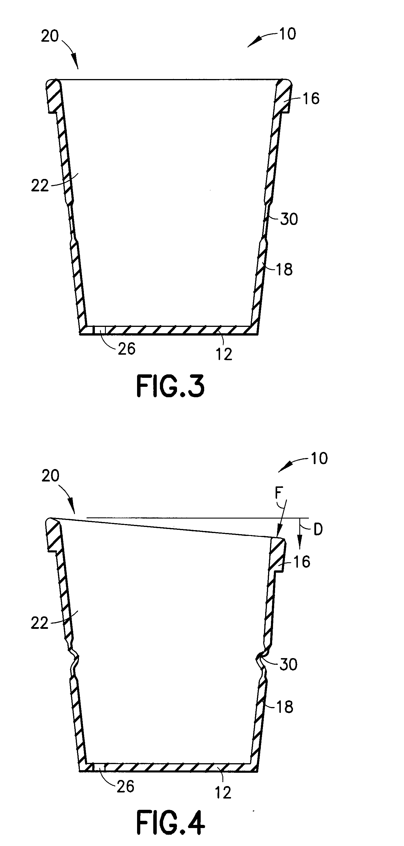
[0022] As shown in FIGS. 1 and 2, a container for containing wood therein, generally referred to by the reference number 10, includes a substantially circular base 12 for supporting a splitting block 14 thereon. The container 10 includes a substantially annular shaped resilient rim 16 and a resilient wall 18 extending between the base 12 and the resilient rim. The resilient rim 16 defines an opening 20 and cooperates with the resilient wall 18 to form an interior area 22 for containing wood 24 therein. The base 16 includes a drain port 26 for allowing water or other fluids to drain out of the container 10. A plug 28 is shown installed in the drain port 26, for use in other applications such as for retaining water and ice.

[0023] In one embodiment, the container 10 has a height H of about 30 inches, a base B having an outside diameter of about 20 inches and the opening 20 having an outside diameter W of about 24 inches. Prior to splitting, the wood 24 is positioned on the splitting b...


PUM

PropertyMeasurementUnit
diameteraaaaaaaaaa
diameteraaaaaaaaaa
heightaaaaaaaaaa

Abstract

A container for use in splitting wood including a base for supporting a splitting block thereon. The container includes a resilient rim and a resilient wall extending between the base and the resilient rim. The resilient rim defines an opening and cooperates with the resilient wall to form an interior area for containing wood therein during a splitting operation.

Description

CROSS-REFERENCE TO RELATED APPLICATION [0001] This application claims priority from provisional application Ser. No. 60 / 847,279, filed Sep. 25, 2006, the disclosure of which is incorporated by reference herein, in its entirety.FIELD OF THE INVENTION [0002] The present invention is generally directed to a resilient container and is more specifically directed to an impact resistant flexible container for use in containing wood pieces generated during a wood splitting operation. BACKGROUND OF THE INVENTION [0003] Splitting wood for use as firewood can be done manually with the use of a splitting tool such as an axe or a maul. A piece of wood to be split is positioned on a splitting block and a person swings the splitting tool in a downward striking motion to cause the wood to separate into two or more sections. After the splitting tool strikes the piece of wood, the sections of wood tend to scatter several feet from the splitting block. The scattering causes additional effort because s...

Claims


Application Information

Patent Timeline
Patent Type & Authority Applications(United States)
IPC IPC(8): B65D8/04B23P17/04B65D8/00
CPCY10T29/49B27L7/08
Inventor BROUARD, ROGER
Owner VETO PRO PAC
Why Eureka
Try Eureka