Eureka AIR delivers breakthrough ideas for toughest innovation challenges, trusted by R&D personnel around the world.

Connecting structure of a liquid sending apparatus, fuel-cell type electricity generating apparatus, and electronic device

Inactive Publication Date: 2008-03-27
CASIO COMPUTER CO LTD
View PDF0 Cites 2 Cited by
  • Summary
  • Abstract
  • Description
  • Claims
  • Application Information

AI Technical Summary

Benefits of technology

[0011]The present invention provides a connecting structure of a compact liquid sending apparatus capable of excellently eliminating bubbles generated by an electrode of an electroosmotic flow pump, a fuel-cell type electricity generating apparatus using the connecting structure of the liquid sending apparatus, and an electronic device having the fuel-cell type electricity generating apparatus.

Problems solved by technology

That is, if liquid comes into contact with the dielectric of the electroosmosis material 502, a surface of the dielectric is electrically charged, counter ions in the liquid gather around the contact interface, and the number of electric charges becomes excessively large.
However, if a liquid-sending operation is continued by the electroosmotic flow pump, bubbles are generated due to electrolysis of liquid in the vicinity of both the electrodes.
Thus, bubbles generated around the upstream electrode are accumulated on the upstream side, an effective flow-path area of the electroosmosis material is reduced and there is a fear that the liquid sending efficiency is deteriorated.
Bubbles generated around the downstream electrode flows downstream together with liquid, there is a fear that a flow rate sensor provided downstream can not detect a precise flow rate of liquid due because bubbles pass.

Method used


Image

  • Connecting structure of a liquid sending apparatus, fuel-cell type electricity generating apparatus, and electronic device
  • Connecting structure of a liquid sending apparatus, fuel-cell type electricity generating apparatus, and electronic device
  • Connecting structure of a liquid sending apparatus, fuel-cell type electricity generating apparatus, and electronic device

Examples


embodiment 1

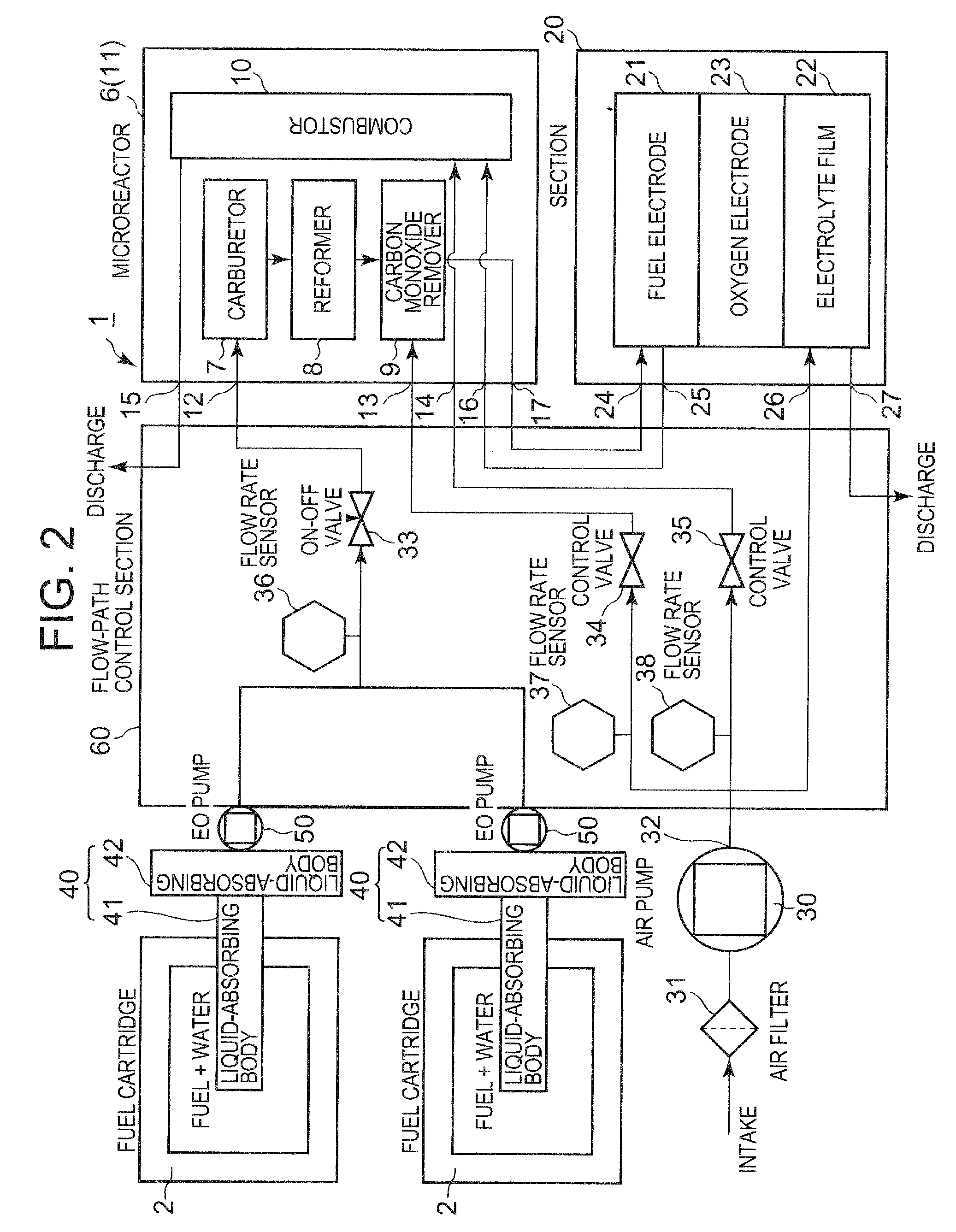
[0111]The T020A produced by Advantech as the hydrophobic film and SUPOR-450 produced by Nihon Pall Ltd as the hydrophilic film were combined with each other and used, and it was confirmed that liquid flowed to the downstream side flow-path through the hydrophilic film, and bubbles were discharged out from the oxygen removing passage formed in an outer side of the inlet-side flow-path structure and from the hydrogen removing passage formed in an outer side of the outlet-side flow-path structure through the hydrophobic film and ventilation hole by the internal pressure.

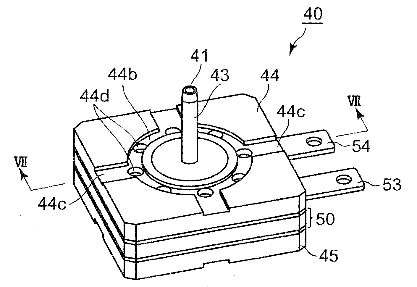
[0112]Although three slits 41c are formed in the disk portion 41b of the first liquid-absorbing body 41 in the above embodiment as shown in FIGS. 9 and 10, more slits 41d (six in FIGS. 14 and 15) may be formed, the second liquid-absorbing body 42 may also be formed with slits (not shown) so that bubbles can be discharged more easily as shown in FIGS. 14 and 15.

[0113]A plurality of through holes 42e may be formed radiall...


PUM


Abstract

Disclosed is a connecting structure of a liquid sending apparatus, including: an electroosmotic flow pump having first and second electrodes upstream and downstream of an electroosmosis material; a flow-path structure which defines with flow-paths for liquid upstream and downstream of the electroosmotic flow pump, which is provided upstream of the electroosmotic flow pump with a ventilation hole communicating with inside and outside of the flow-path, and which is provided with a hydrophobic film which covers the hole and is permeable to bubbles; and a liquid-absorbing body absorbs liquid, which is provided in the flow-path upstream of the electroosmotic flow pump, which comes into abutment against a surface of the electroosmosis material on which the first electrode is provided, and which is formed with a bubble removing passage which passes through the liquid-absorbing body from a hydrophobic film side thereof to the abutment surface against the electrode.

Description

BACKGROUND OF THE INVENTION[0001]1. Field of the Invention[0002]The present invention relates to a connecting structure of a liquid sending apparatus having an electroosmotic flow pump using an electroosmosis phenomenon, a fuel-cell type electricity generating apparatus having the connecting structure of the liquid sending apparatus, and an electronic device having the fuel-cell type electricity generating apparatus.[0003]2. Description of Related Art[0004]In recent years, fuel-cells receive attention as clean power supplies having high energy conversion efficiency, and the fuel-cells become commercially practical for fuel-cell automobiles, portable devices, electrical houses.[0005]In the fuel-cell, a pump is used as a power source for sending fuel or water. There are centrifugal type pumps, volume rotary type pumps, volume reciprocating type pumps which are mechanically operated. For example, Japanese Patent Application Laid-open No. 2006-22807 discloses an electroosmotic flow pump...

Claims


Application Information

Patent Timeline
IPC IPC(8): H01M8/02F04F11/00F04F99/00
CPCF04B17/00F04B19/006Y02E60/50H01M8/04208H01M8/0618H01M8/04201Y10T137/85978
Inventor SUNAKO, TAKAYUKIKABASAWA, YASUNARIYANAGISAWA, ICHIRO
Owner CASIO COMPUTER CO LTD
Why Eureka
Eureka Blog
Learn More