Ladder Rack Assembly

a ladder rack and assembly technology, applied in the field of ladder racks, can solve the problems of ladder racks often unable to be collapsed down low, ladder racks often occupy floor space, ladder racks often rattle around loosely,

Inactive Publication Date: 2008-04-03
WETHINGTON BRIAN J
View PDF7 Cites 42 Cited by
  • Summary
  • Abstract
  • Description
  • Claims
  • Application Information

AI Technical Summary

Benefits of technology

[0006] The present invention provides a rack assembly for at least partially supporting a ladder in the bed box of a truck. In one embodiment, the rack assembly includes a telescopically erectable and collapsible stanchion assembly, at least one bracket assembly for mounting the bottom of the stanchion assembly to the truck's bed box, and a telescopically extendable and retractable crossbar assembly that is releasably securable at the top of the stanchion assembly. When the rack assembly is not being used, tubular sections of the stanchion assembly can be telescopically collapsed together. Tubular sections of the crossbar assembly can be released from the top of the stanchion assembly and then placed in the collapsed stanchion assembly. In this way, the rack assembly can be stored in a substantially unitary, reduced-volume configuration in the bed box of the truck.

Problems solved by technology

After taking down a ladder rack, however, the demounted ladder rack often undesirably takes up floor space in a truck's bed box, and the ladder rack often rattles around loosely in the truck's bed while driving.
Though such conventional ladder racks do help conserve some floor space in a truck's bed box and also reduce rattle, such ladder racks often cannot be collapsed down low enough to permit a truck bed cover to be mounted over a bed box.
Also, such ladder racks often undesirably require that their crossbar assemblies still be detached and laid loosely in a truck's bed.

Method used


Image

  • Ladder Rack Assembly
  • Ladder Rack Assembly
  • Ladder Rack Assembly

Examples


Embodiment Construction

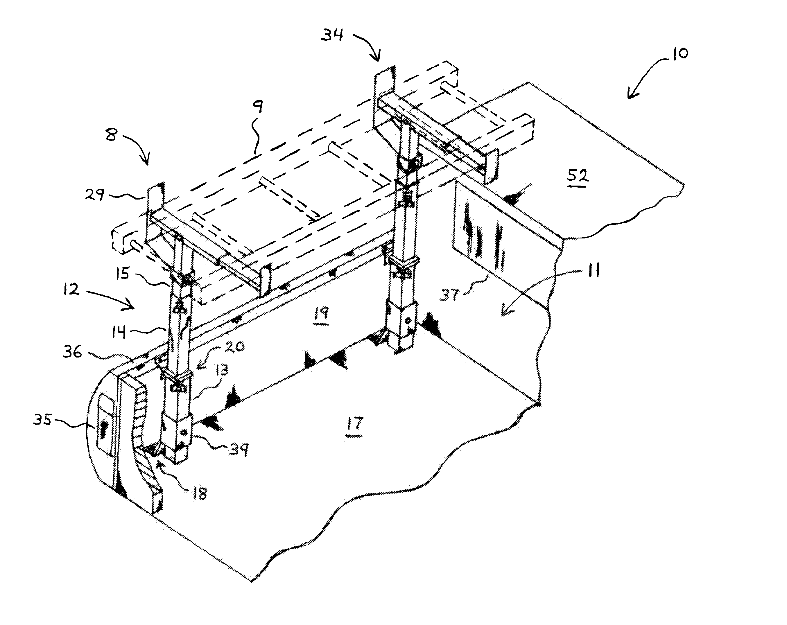
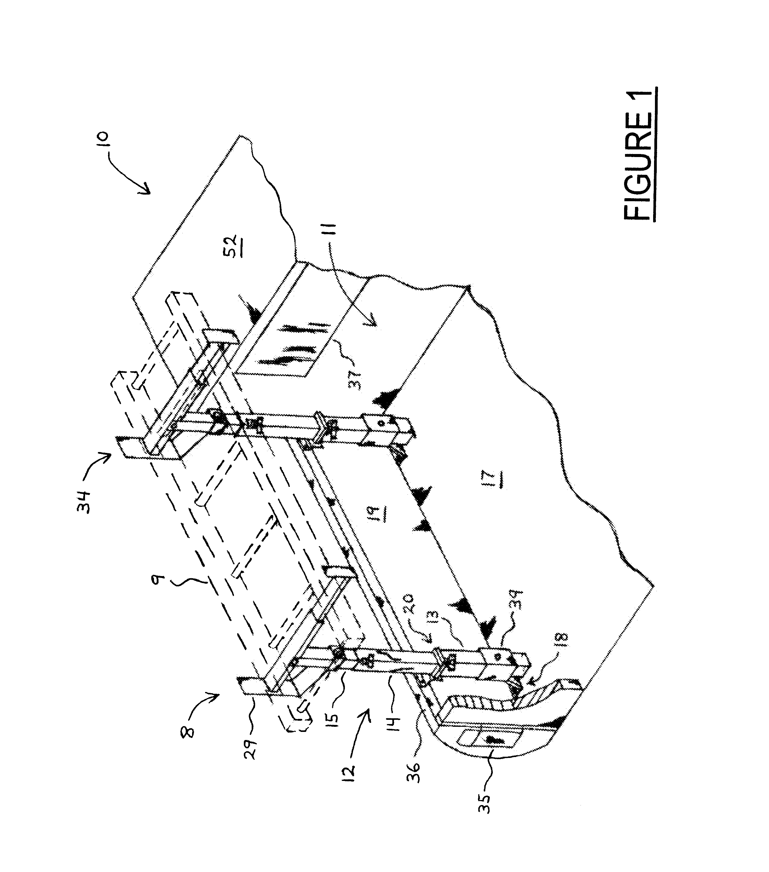
[0062]FIGS. 1 through 7 illustrate various views of one embodiment of a rack assembly 8 according to the present invention. In general, the rack assembly 8 is utile for at least partially supporting a ladder 9 in the bed box 11 of a truck 10. As shown, the rack assembly 8 includes a stanchion assembly 12, a first bracket assembly 18, a second bracket assembly 20, and a crossbar assembly 21.

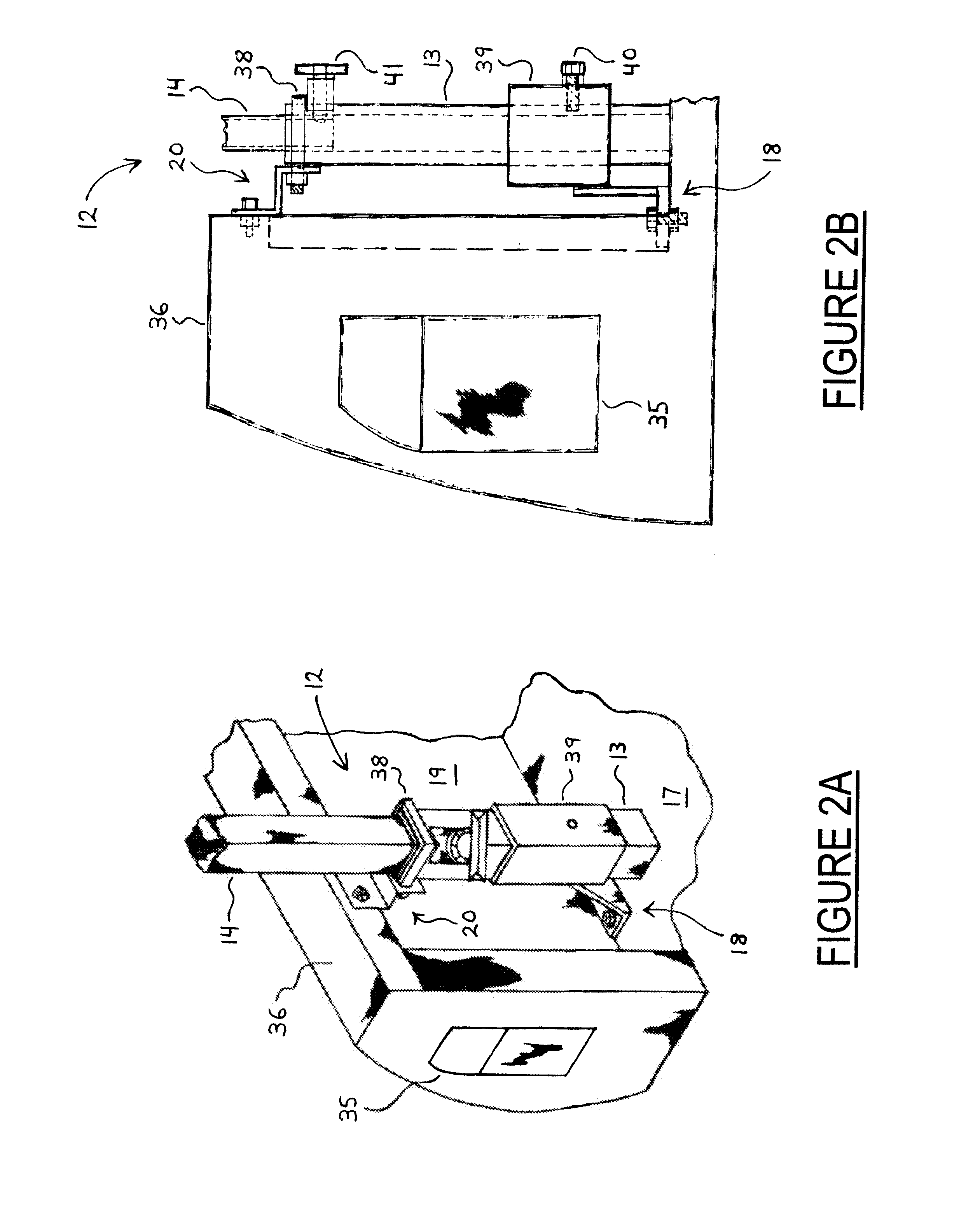
[0063] The stanchion assembly 12 is telescopically erectable and collapsible. In general, the stanchion assembly 12 has a bottom tubular section 13, a middle tubular section 14, and a top tubular section 15. The top tubular section 15 has a top end 16 that is substantially open and hollow.

[0064] The first bracket assembly 18 is adapted for mounting the bottom tubular section 13 of the stanchion assembly 12 to the floor 17 of the truck's bed box 11. As best shown in FIGS. 2A and 2B, the first bracket assembly 18 particularly includes both a square tubing weldment 39 and a compression bolt 40 to a...


PUM


Abstract

A rack assembly for at least partially supporting a ladder in the bed box of a truck is disclosed herein. The rack assembly includes a telescopically erectable and collapsible stanchion assembly, at least one bracket assembly for mounting the bottom of the stanchion assembly to the truck's bed box, and a telescopically extendable and retractable crossbar assembly that is releasably securable at the top of the stanchion assembly. When the rack assembly is not being used, tubular sections of the stanchion assembly can be telescopically collapsed together. Tubular sections of the crossbar assembly can be released from the top of the stanchion assembly and then placed in the collapsed stanchion assembly. In this way, the rack assembly can be stored in a substantially unitary, reduced-volume configuration in the bed box of the truck.

Description

CROSS REFERENCE TO A RELATED APPLICATION [0001] The present invention claims priority from U.S. Provisional Application Ser. No. 60 / 847,990, originally entitled “Collapsible and Detachable Mounted Ladder Rack,” which was filed on Sep. 28, 2006.FIELD OF THE INVENTION [0002] The present invention generally relates to a rack for supporting and transporting a ladder onboard a vehicle. The present invention more particularly relates to a ladder rack assembly that is collapsible onboard a vehicle. BACKGROUND OF THE INVENTION [0003] Ladder racks are frequently mounted in the beds or bed boxes of trucks so that work ladders can be easily supported, secured, and transported onboard trucks without rattling around loose in the trucks' beds while traveling to work sites. When, however, a ladder rack is not being utilized to transport a ladder, it is generally desirable to take the ladder rack down so as to help conserve space in a truck's bed box, or so that a truck bed cover can be placed over...

Claims


Application Information

Patent Timeline
Patent Type & Authority Applications(United States)
IPC IPC(8): B60P1/00
CPCB60P3/40B60R9/0485B60R9/00
Inventor WETHINGTON, BRIAN J.
Owner WETHINGTON BRIAN J
Why Eureka
Try Eureka