Golf club head structure

a golf club and head technology, applied in the field of golf club head, can solve the problems of golf ball flying non-smoothly and in the wrong direction, golf ball is relatively difficult to make an accurate golf shot with the golf club, and the golfer's hands are injured, so as to increase the ability of the club head to bear force and reduce the reaction of the golf ball.

Inactive Publication Date: 2008-04-10
SWING SCI
View PDF3 Cites 40 Cited by
  • Summary
  • Abstract
  • Description
  • Claims
  • Application Information

AI Technical Summary

Benefits of technology

[0009]The golf club head of the present invention consists of a shell part, and a face part. The shell part has a front opening, a holding hollowness behind the front opening, a few strengthening pieces in the holding hollowness, and a slot on an upper side thereof, which communicates with the holding hollowness. The shell part further has several connecting blocks, which are received in the slot, and each connected to two lateral sides of the slot, for increasing capability of the club head to bear force. The face part is closely fitted in the front opening of the shell part, and propped by means of the strengthening pieces in the holding hollowness. Furthermore, a kind of elastic shock absorbing material is injected in the holding hollowness of the shell part to prop the face part. Because the club head has shock absorbing function with the elastic shock absorbing material, the golf ball will fly smoothly if a golfer swings the golf club to hit a golf ball in a correct way. And, the reaction of the golf ball will be significantly reduced, prevented from causing discomfort and injury to the golfer's hands.

Problems solved by technology

1. Because both the golf club head and golf balls are very hard, and the club head doesn't have any shock absorbing function, a golf ball will probably fly non-smoothly and in a wrong direction even if the golfer swings the golf club to hit the golf ball in a correct way. In other words, it is relatively difficult to make an accurate golf shot with the golf club.
2. When a golfer hits a golf ball with the golf club, the reaction of the golf ball on the club will be passed on to and cause discomfort and even injury to the golfer's hands because the club head doesn't have any shock absorbing function. In other words, the golf club isn't relatively safe to use.

Method used


Image

  • Golf club head structure
  • Golf club head structure
  • Golf club head structure

Examples


Embodiment Construction

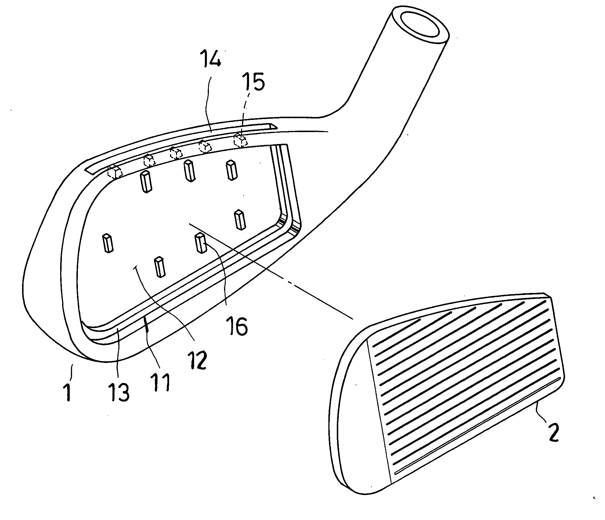
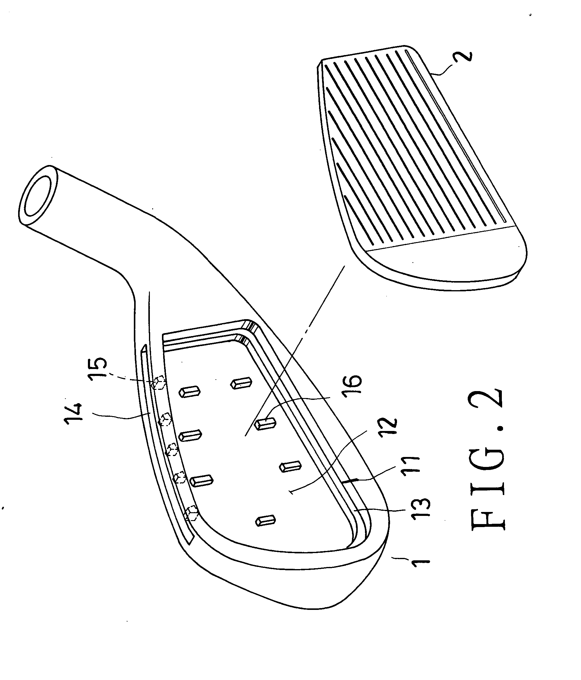
[0015]Referring to FIGS. 2 to 4, a preferred embodiment of a head of a golf club consists of a shell part 1, and a face part 2. The shell part 1 is made of metallic materials, e.g. stainless steel, by means of casting. The shell part 1 has a front opening 11, a truncated cone shaped inner circumferential side around the front opening 11, a holding hollowness 12 behind the front opening 11, and a protruding portion 13 on an inward end of the truncated cone shaped inner circumferential side. Furthermore, the shell part 1 has a slot 14 on an upper side thereof, which communicates with the holding hollowness 12. The slot 14 has several connecting blocks 15 therein, which are each connected to two lateral sides of the slot 14. A few strengthening pieces 16 are held in the holding hollowness 12. Therefore, the upper portion of the club head, on which the slot 14 and the connecting blocks 15 are provided, can bear more force, preventing damage and deformation to the club head if the golf c...


PUM


Abstract

A golf club head consists of a shell part, and a face part; the shell part has a front opening, a holding hollowness behind the front opening, several strengthening pieces in the holding hollowness, and a slot on an upper side, which communicates with the holding hollowness; the slot of the shell part has several connecting blocks therein, which are each connected to two lateral sides of the slot, for increasing capability of the shell part to bear force; the face part is closely fitted in the front opening of the shell part, and propped by means of the strengthening pieces in the holding hollowness; and, a kind of elastic shock absorbing material is injected in the holding hollowness of the shell part to prop the face part.

Description

BACKGROUND OF THE INVENTION[0001]1. Field of the invention[0002]The present invention relates to a golf club head, more particularly one, which will help a golfer make a golf ball fly smoothly, and reduce reaction of the golf ball, thus preventing the golfer's hands from being subjected to shock, discomfort and injury.[0003]2. Brief Description of the Prior Art[0004]Referring to FIG. 1, a conventional golf club head consists of a shell part 91, and a face part 92. The shell part 91 is made of metallic materials such as stainless steel by means of casting. The shell part 91 has a front opening 911, a truncated cone shaped inner circumferential side around the front opening 911, a holding hollowness 912 behind the front opening 911, and a protruding portion 913 on an inward portion of the truncated cone shaped inner circumferential side. The face part 92 is secured in the front opening 911 of the shell part 91, closely touching the truncated cone shaped inner circumferential side and ...

Claims


Application Information

Patent Timeline
Patent Type & Authority Applications(United States)
IPC IPC(8): A63B53/00
CPCA63B53/047A63B53/0475A63B2053/0454A63B2053/045A63B2053/0416A63B59/0092A63B60/54A63B53/0454A63B53/045A63B53/0416
Inventor IWAHORI, MOTOFUSA
Owner SWING SCI
Why Eureka
Try Eureka