Impact Attenuating and Spring Elements and Products Containing such Elements

a technology of spring elements and attenuating springs, which is applied in the direction of elastic dampers, shock absorbers, machine supports, etc., can solve the problems of preventing or slowing the recovery of materials, causing the shoe to stand too tall vertically, and reducing the energy of materials back to the shoe user

Active Publication Date: 2008-05-01
NIKE INC
View PDF53 Cites 28 Cited by
  • Summary
  • Abstract
  • Description
  • Claims
  • Application Information

AI Technical Summary

Benefits of technology

[0013] Additional aspects of the invention relate to methods for including impact attenuating and spring elements in products, such as in pieces of footwear or other foot-receiving devices. Such methods may include, for example: (a) providing an upper member and a sole member for a piece of footwear or other foot-receiving device; (b) selecting at least a portion of an impact attenuating and spring element (e.g., at least a spring member) at least in part based on a characteristic of an intended user of the piece of footwear or other foot-receiving device (e.g., user weight, foot width, running/walking speed capabilities, jumping capabilities, typical gait or stride characteristics (e.g., a pronation or supination tendency, etc.), etc.), or a characteristic of an intended use of the piece of footwear or other foot-receiving device (e.g., for a specific sport o...

Problems solved by technology

An excessively high volume of impact attenuating material, if necessary to adequately attenuate ground reaction forces and/or provide support, may make the shoe stand too tall vertically, particularly for use as an athletic shoe.
Moreover, even when conventional foam materials provide ad...

Method used


Image

  • Impact Attenuating and Spring Elements and Products Containing such Elements
  • Impact Attenuating and Spring Elements and Products Containing such Elements
  • Impact Attenuating and Spring Elements and Products Containing such Elements

Examples


Embodiment Construction

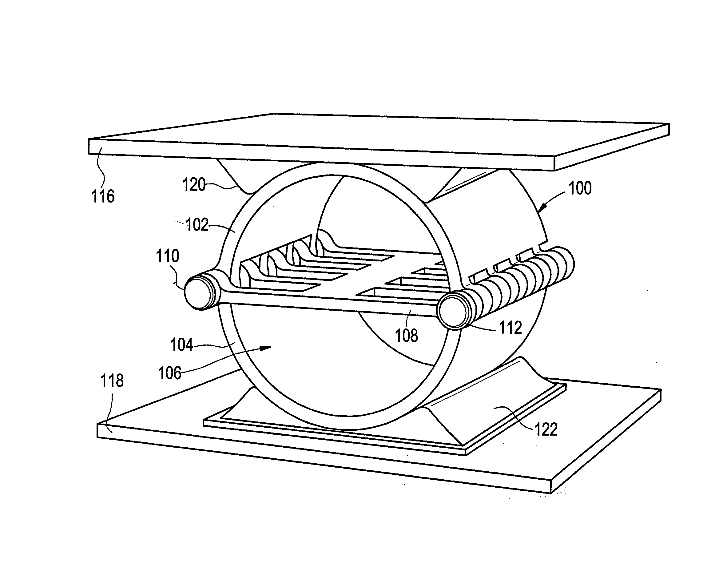
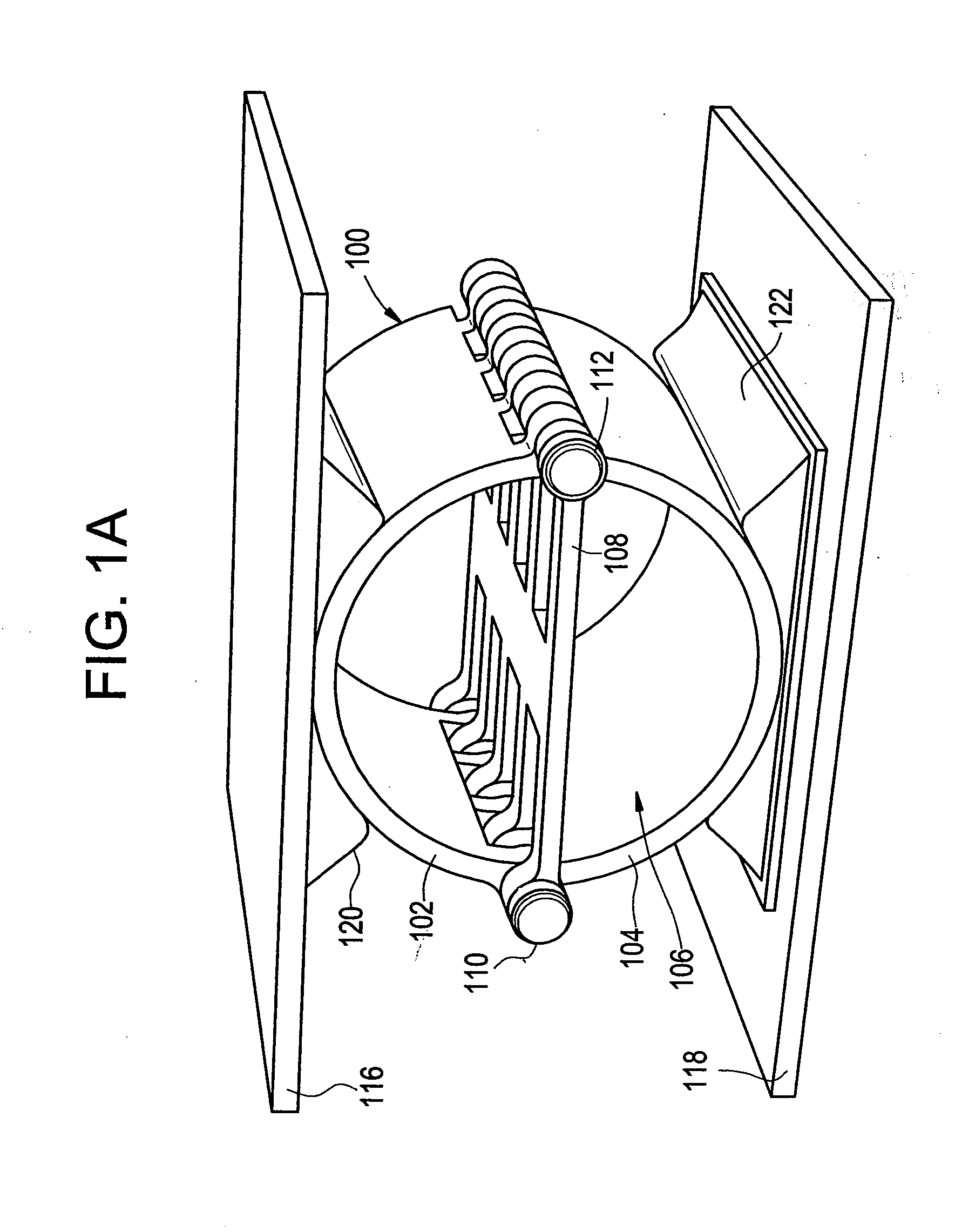
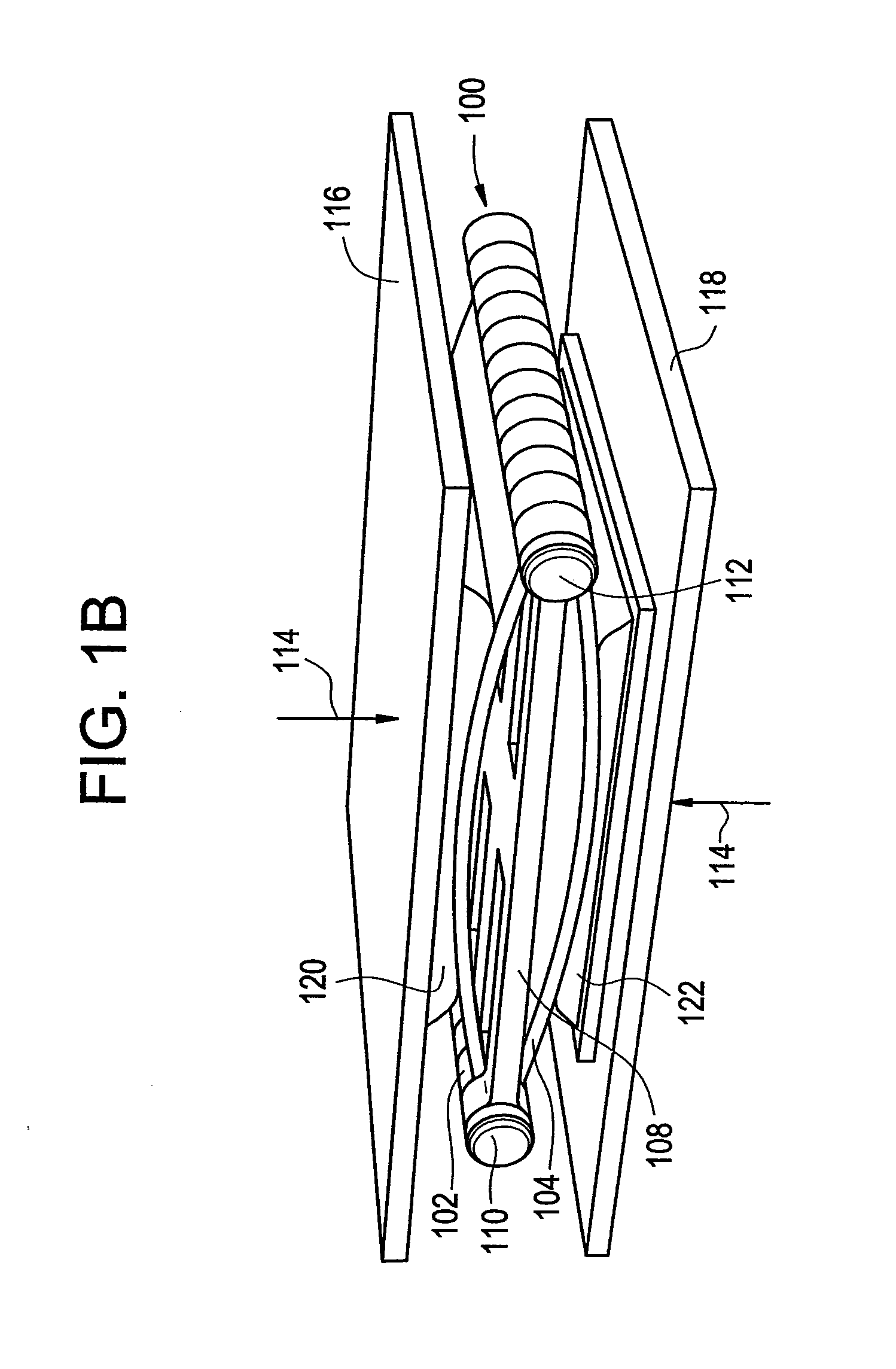
[0026] In the following description of various examples of the invention, reference is made to the accompanying drawings, which form a part hereof, and in which is shown by way of illustration various example systems and environments in which the invention may be practiced. It is to be understood that other specific arrangements of parts, example systems, and environments may be utilized and structural and functional modifications may be made without departing from the scope of the present invention. Also, while the terms “top,”“bottom,”“side,”“front,”“back,” and the like may be used in this specification to describe various example features and elements of the invention, these terms are used herein as a matter of convenience, e.g., based on the example orientations shown in the figures. Nothing in this specification should be construed as requiring a specific three dimensional orientation of structures in order to fall within the scope of this invention.

[0027] To assist the reader...


PUM


Abstract

Impact attenuating/spring systems may include first and second body portions and at least one spring member at least partially included between the body portions. The spring member(s) may substantially enclose and/or be pivotally engaged with the body portion(s). The components of the impact attenuating and spring element may be arranged such that when a force is applied to the body portion(s), the spring member(s) will exert a counter force to urge the impact attenuating and spring element back toward its original orientation. The spring members may include one or more polymeric element that stretches under a tensile force. The impact attenuating and spring elements may be included in a piece of footwear or other device in a manner such that a user or a retailer (or others) can select an appropriate spring member (or portion thereof), e.g. depending on characteristics of the user or the intended use.

Description

CROSS-REFERENCE TO RELATED APPLICATION [0001] This application is a divisional of co-pending U.S. patent application Ser. No. 10 / 949,812 filed on Sep. 27, 2004, the contents of which are incorporated herein by reference in its entirety.FIELD OF THE INVENTION [0002] The invention relates generally to impact attenuating and spring elements. Such elements may be provided in a wide variety of different products, e.g., in footwear products and other foot-receiving devices, such as in the heel and / or toe areas of footwear products. This application generally relates to impact attenuating elements like those described in concurrently filed U.S. patent application Ser. No. 10 / 949,813, entitled “Impact Attenuating Devices and Products Containing Such Devices,” naming Michael Aveni as an inventor (Attorney Docket No. 005127.00401). This concurrently filed U.S. patent application is entirely incorporated herein by reference. BACKGROUND [0003] Conventional articles of athletic footwear have inc...

Claims


Application Information

Patent Timeline
IPC IPC(8): F16F7/12F16F3/00A43B13/18
CPCA43B13/183A43B13/184A43B7/32A43B13/181F16F7/00A43B21/26
Inventor SMALDONE, PATRICIA LOUISEAVENI, MICHAEL A.FAGERGREN, FRED G.
Owner NIKE INC
Why Eureka
Try Eureka