Thermal transfer line printer

a technology of thermal transfer line printer and transmission path, which is applied in the direction of printing, instruments, measurement devices, etc., can solve the problems of inability to perform precise conveyance, inability to perform high-quality recording, and large amount of backlash, so as to reduce the total number of gears between a driving member and a driving member. , the amount of backlash of a driving force transmission path can be reduced, and the effect of easy and reliable control of the amount of backlash

Active Publication Date: 2008-05-01
ALPS ALPINE CO LTD
View PDF3 Cites 8 Cited by
  • Summary
  • Abstract
  • Description
  • Claims
  • Application Information

AI Technical Summary

Benefits of technology

[0025]A thermal transfer line printer according to an aspect of the disclosure includes: a platen roller to which the driving force of a driving motor is transmitted, and that is rotationally driven in the forward rotation direction or reverse rotation direction. A line thermal head is provided so as to face the platen roller and so as to be brought close to or separated from the platen roller. One pair of conveying rollers are rotatably disposed with the platen roller therebetween. A re-transmission mechanism is provided that re-transmits the driving force, which is transmitted to the platen roller from the driving motor, to each of the one pair of conveying rollers. Here, the re-transmission mechanism has a driving force transmission gear mounted on the platen roller, a driven roller mounted on each of the one pair of conveying rollers, and an intermediate gear that always meshes with both the driving force transmission gear and the driven roller. Each of the one pair of conveying rollers is formed so as to be rotationally driven in the same direction as the direction of rotation of the platen roller. The intermediate gear is rotatably supported by a gear supporting shaft, and the gear supporting shaft is adjusted in position so that both the center distance between the axis of the intermediate gear and the axis of the driving force transmission gear and the center distance between the axis of the intermediate gear and the axis of the driven roller can be adjusted. By adopting such a configuration, a driving force transmitted to the platen roller is re-transmitted to the one pair of conveying rollers, so that each of the one pair of conveying rollers can be driven to follow the platen roller. Thus, the platen roller and the one pair of conveying rollers can be driven by one driving motor. Also, the total number of gears between a driving member and a driven member can be reduced, and the amount of the backlash of a driving force transmission path can be reduced. Moreover, the numbers of gears in the driving force transmission paths from the platen roller to the one pair of conveying rollers, respectively, can be made equal to each other. Therefore, the amounts of backlash in the driving force transmission paths can be made equal to each other. Furthermore, the position of the gear supporting shaft can be adjusted. Thus, it is possible to easily and reliably control the amount of the backlash between the intermediate gear and the driving force transmission gear, and the amount of the backlash between the intermediate gear and the driven roller.
[0026]Preferably, the position of both ends of the gear supporting shaft after positional adjustment is fixed. By adopting such a configuration, it is possible to reliably prevent the gear supporting shaft from being displaced due to a load applied to the intermediate gear, etc. Preferably, a distal end of the gear supporting shaft is formed so as to be able to be fixed without applying the force that will bend the gear supporting shaft. By adopting such a configuration, the distal end of the gear supporting shaft can be fixed firmly.
[0027]According to the thermal transfer line printer of the aspect of the disclosure, conveyance unevenness of a recording medium hardly occurs. Thus, high-quality recording can be performed easily and reliably.

Problems solved by technology

Thus, there is a problem in that, as the total number of meshing portions between teeth interposed between a driving member, such as a motor, and driven members, such as the conveying rollers 106 and 107, becomes more, the total amount of the backlash become large, consequently uneven conveyance of the recording medium 104 occurs, and thus exact conveyance cannot be performed.
As a result, when full color recording is performed on the recording medium 104, there is also a fear that color deviation is caused in different ink colors on an ink film 103 where overlapping recording is made, and thus high-quality recording cannot be performed.
Therefore, there is also a problem in that deviation may be caused between the starting timing of the first conveying roller and the starting timing of the second conveying roller 107 due to a difference in the amount of backlash.
In addition, in the conventional thermal transfer line printer 101, there is also a problem in that the first driving motor that drives the first and second conveying rollers 106 and 107, and the second driving motor that drives the platen roller 102 are provided independently, and a need for reducing cost cannot be met.

Method used


Image

  • Thermal transfer line printer
  • Thermal transfer line printer
  • Thermal transfer line printer

Examples


Embodiment Construction

[0039]Hereinafter, the invention will be described by the embodiments shown in the drawings.

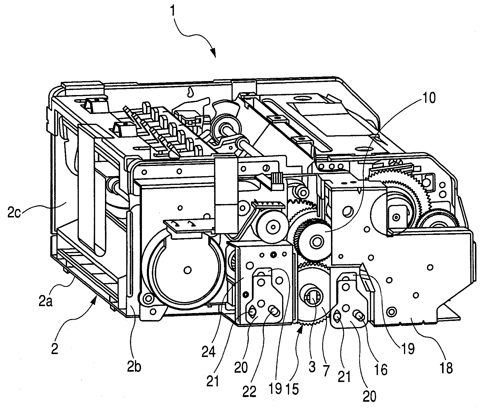
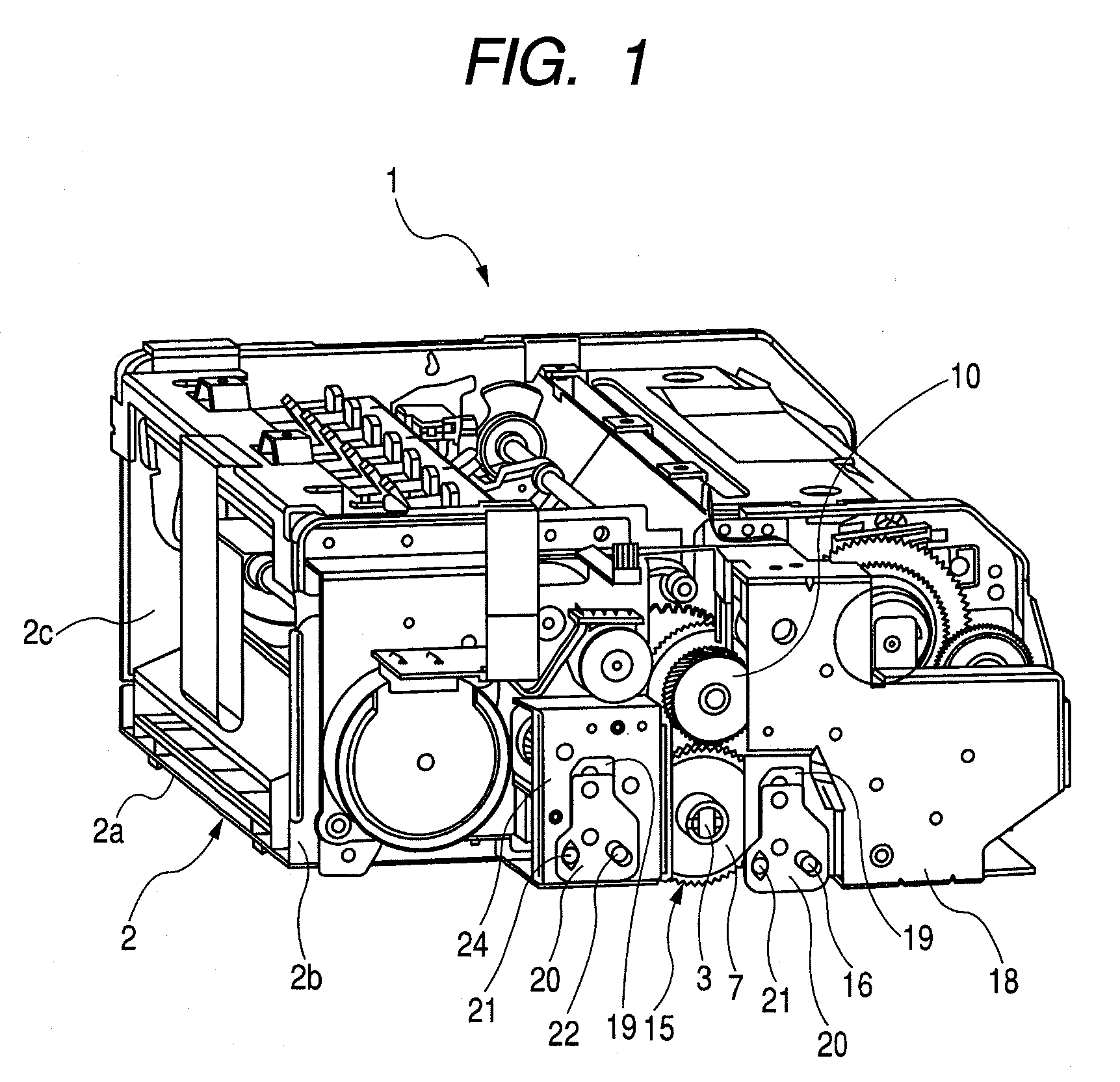
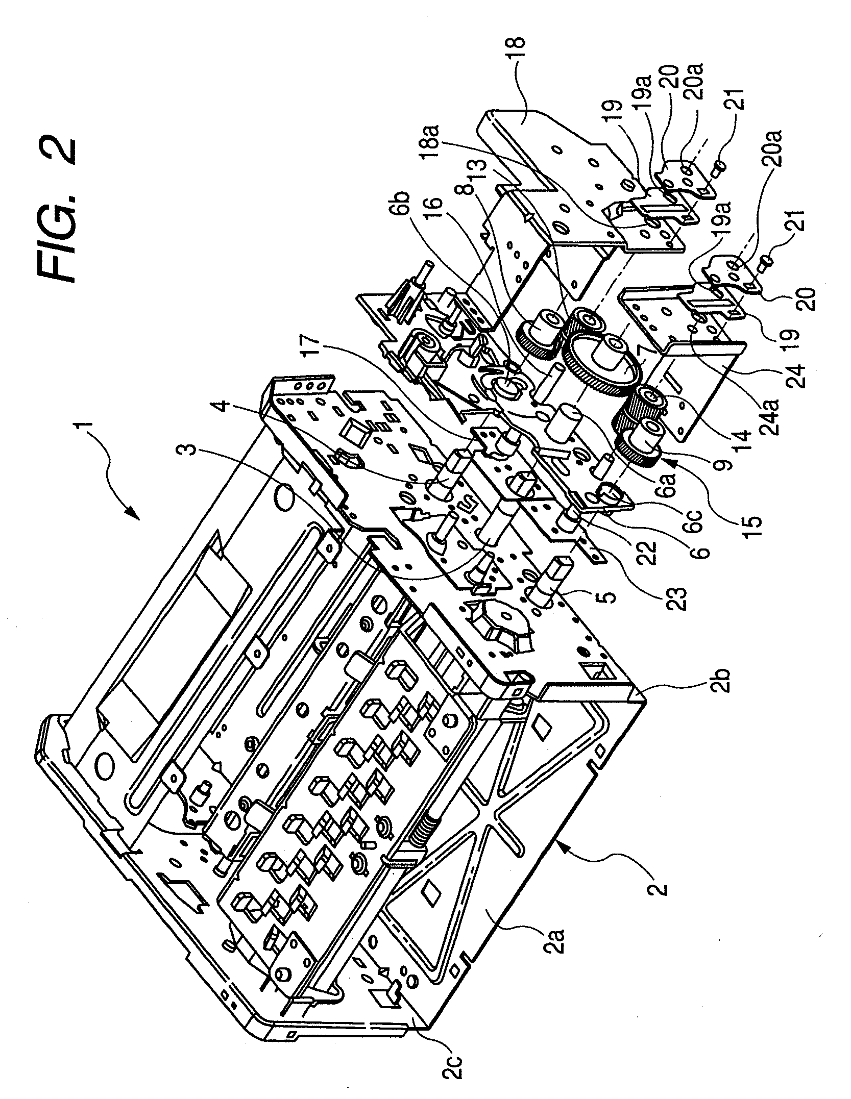
[0040]FIGS. 1 to 2 show a thermal transfer line printer according to an embodiment of the disclosure. Specifically, FIG. 1 is an external perspective view showing essential parts, FIG. 2 is a partially exploded and enlarged perspective view of the essential parts, FIG. 3 is a front view in the vicinity of a re-transmission mechanism, FIG. 4 is an enlarged perspective view in the vicinity of a first gear pivot, FIG. 5 is an enlarged front view of a lower plate, FIG. 6 is an enlarged front view of an upper plate, FIG. 7 is an enlarged front view showing a state where the upper plate is superposed on the lower plate, FIG. 8 is an enlarged front view showing an example of a state where the position of the upper plate superposed on the lower plate has been moved, and FIG. 9 is an enlarged perspective view in the vicinity of a second gear pivot.

[0041]As the thermal transfer line printer of the pres...


PUM


Abstract

A printer capable of printing high-quality recording is provided. A driving force transmission gear mounted on a platen roller, driven rollers mounted on a pair of conveying rollers, respectively, and intermediate gears that always mesh with both the driving force transmission gear, and the driven rollers form a re-transmission mechanism that re-transmits the driving force transmitted to the platen roller from a driving motor to each of the one pair of conveying rollers. Also, gear supporting shafts that rotatably support intermediate gears are configured so as to be adjustable in position.

Description

CLAIM OF PRIORITY[0001]This application claims benefit of the Japanese Patent Application No 2006-297853 filed on Nov. 1, 2006, which is hereby incorporated by reference.BACKGROUND[0002]1. Field of the Invention[0003]The present invention relates to a thermal transfer line printer, and particularly, to a small-sized thermal transfer line printer that can reciprocate a recording medium to form a full color image on the surface of the recording medium.[0004]2. Description of the Related Art[0005]Conventionally, a thermal transfer line printer that can perform recording in a direction orthogonal to the conveying direction of a recording medium by means of a line thermal head having a length corresponding to the recording ranges of a recording medium in its longitudinal and transverse directions is known (for example, refer to JP-A-08-072335 (FIG. 1)).[0006]FIG. 11 shows an example of a conventional thermal transfer line printer. This conventional thermal transfer line printer 101 is co...

Claims


Application Information

Patent Timeline
Patent Type & Authority Applications(United States)
IPC IPC(8): B41J2/33
CPCB41J13/036B41J11/42
Inventor ABE, YOSHIBUMIONOZATO, TAKASHISATO, MINORUMOTOKI, ZENKOARAUCHI, SUSUMU
Owner ALPS ALPINE CO LTD
Why Eureka
Try Eureka