System and method for removal of buried objects

a technology for buried objects and removal methods, applied in nuclear engineering, applications, caissons, etc., can solve the problems of difficult retrieval using normal excavation techniques, high radiation risk of vpus, undue risk to workers or the environment, and achieve the effect of minimizing potential radiological or chemical exposure and short tim

Inactive Publication Date: 2008-05-01
NORTHWIND
View PDF23 Cites 16 Cited by
  • Summary
  • Abstract
  • Description
  • Claims
  • Application Information

AI Technical Summary

Benefits of technology

[0009]This invention provides a means for retrieval of waste which encapsulates the waste intact thus minimizing potential radiological or chemical exposures to workers or the public. Furthermore, this invention relies upon commercially available and mature equipment, technologies, a...

Problems solved by technology

Some of these wastes, because of high worker safety risks or significant potential for contamination spread, will be difficult to retrieve using normal excavation techniques.
T...

Method used


Image

  • System and method for removal of buried objects
  • System and method for removal of buried objects
  • System and method for removal of buried objects

Examples


Embodiment Construction

[0039]Referring to the figures, there are depicted some, but not all, embodiments of the present invention.

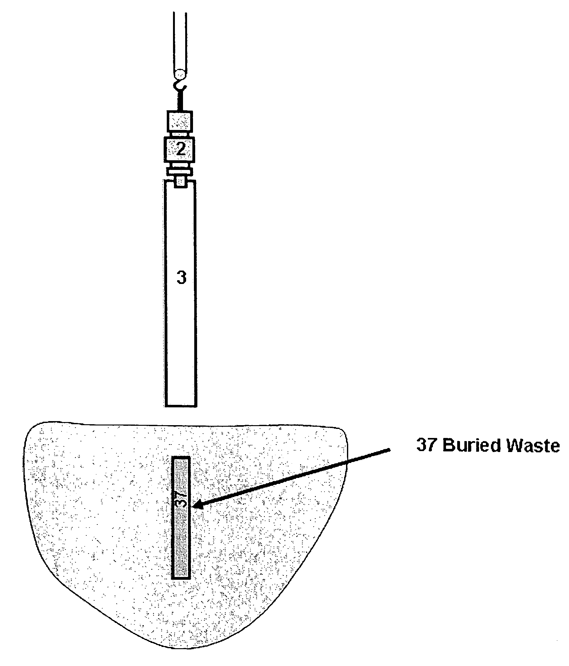
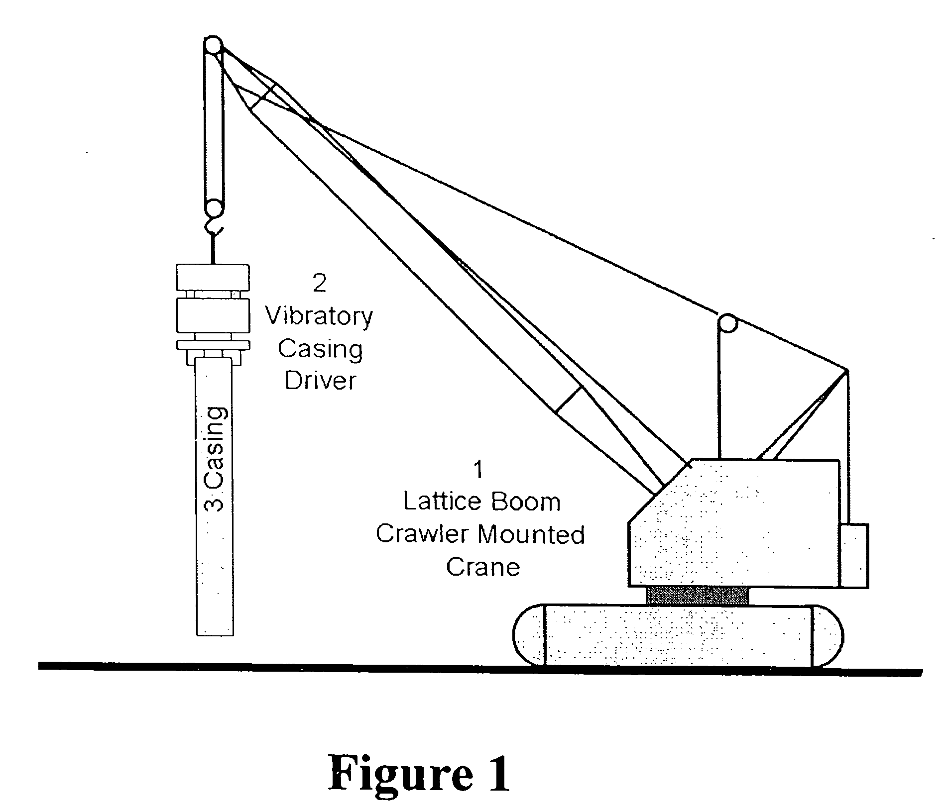
[0040]In FIG. 1, there is depicted crane 1 carrying vibratory casing driver 2, which driver 2 is connected to casing 3 so that casing 3 is suspended over the ground.

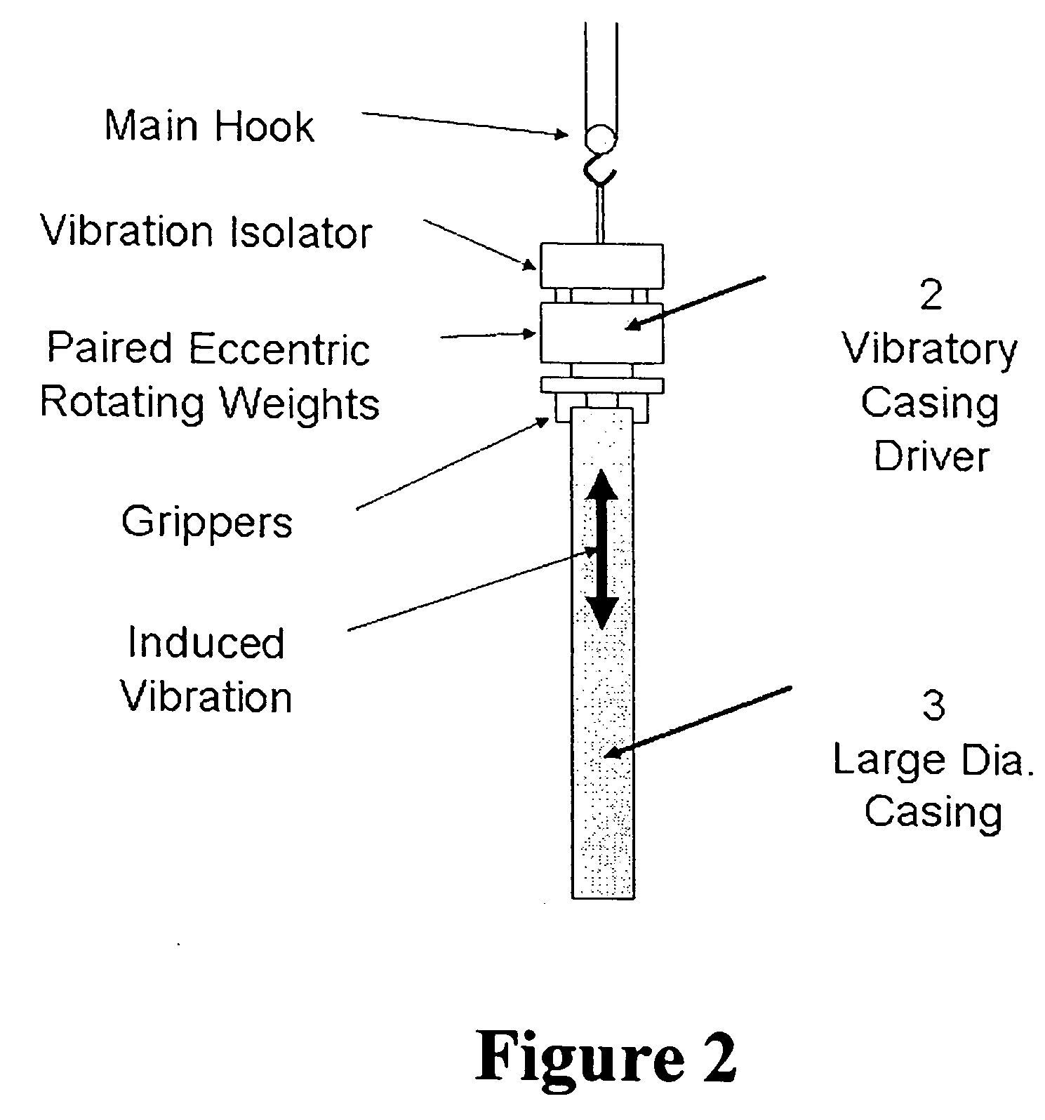
[0041]FIG. 2 is a more detailed view of the vibratory casing driver (2) and casing (3) showing the three main elements of the casing driver (grippers, paired rotating eccentric weights, and vibration isolator). It further shows the up-down direction of induced vibration of the casing. In operation, the casing is attached to the vibratory casing driver with the hydraulic grippers or clamps. As a safety precaution, the casing is also attached loosely to the main hook with one or more slings and shackles (not shown).

[0042]In operation the process begins with establishing the target or location for overcoring (surrounding) the buried waste. At this point a centralizer casing positioning system (see FIG. 11) is preferabl...


PUM


Abstract

The present invention is a system and method for removal of buried objects. According to one embodiment of the invention, a crane with a vibrator casing driver is used to lift and suspend a large diameter steel casing over the buried object. Then the casing is driven into the ground by the vibratory driver until the casing surrounds the buried object. Then the open bottom of the casing is sealed shut by injecting grout into the ground within the casing near its bottom. When the seal has cured and hardened, the top of the casing is lifted to retrieve the casing, with the buried object inside, from the ground.

Description

[0001]This application claims priority from prior, co-pending U.S. Provisional Patent Application No. 60 / 712,755, filed Aug. 29, 2005, the disclosure of which is incorporated herein by reference.[0002]Activities related to this application were conducted under US Department of Energy (DOE) Contract No. DE-AC-09-03NT42006. The U.S. Government may have rights to practice this invention.BACKGROUND OF THE INVENTION[0003]1. Field of the Invention[0004]This invention relates generally to removal of buried objects from the ground. More specifically, this invention relates to surrounding buried waste of a given diameter with a larger diameter casing, sealing the bottom of the casing with grout, and pulling the sealed casing out of the ground with the grout plug intact to retrieve the buried waste.[0005]2. Related Art[0006]U.S. Pat. No. 5,980,446 (Loomis, et al.) discloses a method for injecting grout underground to form solid columns. A series of the columns may be overlapped to surround an...

Claims


Application Information

Patent Timeline
IPC IPC(8): A01D31/00
CPCE02D9/02G21F9/36G21F9/34E02D11/00
Inventor ALEXANDER, ROBERT G.CRASS, DENNISGRAMS, WILLIAMPHILLIPS, STEVEN J.RIESS, MARK
Owner NORTHWIND
Why Eureka
Try Eureka