Confirming Artificial Finger Mechanism

Inactive Publication Date: 2008-05-08
UNIV OF SOUTH FLORIDA
View PDF8 Cites 13 Cited by
  • Summary
  • Abstract
  • Description
  • Claims
  • Application Information

AI Technical Summary

Benefits of technology

[0025]The novel apparatus accomplishes several goals for the amputee. The primary objective of the invention is to achieve versatility in the shapes and sizes of objects that can be grasped. The novel finger/finger tip offers several unique features: self-positioning mechanisms, increased surface contact between the finger tips and the object surface, less energy required to power the gripping mechanism

Problems solved by technology

Amputations of the hand result in chronic disability.
Conventional designs of artificial hands do not perform well at grasping different shapes

Method used


Image

  • Confirming Artificial Finger Mechanism
  • Confirming Artificial Finger Mechanism
  • Confirming Artificial Finger Mechanism

Examples


Embodiment Construction

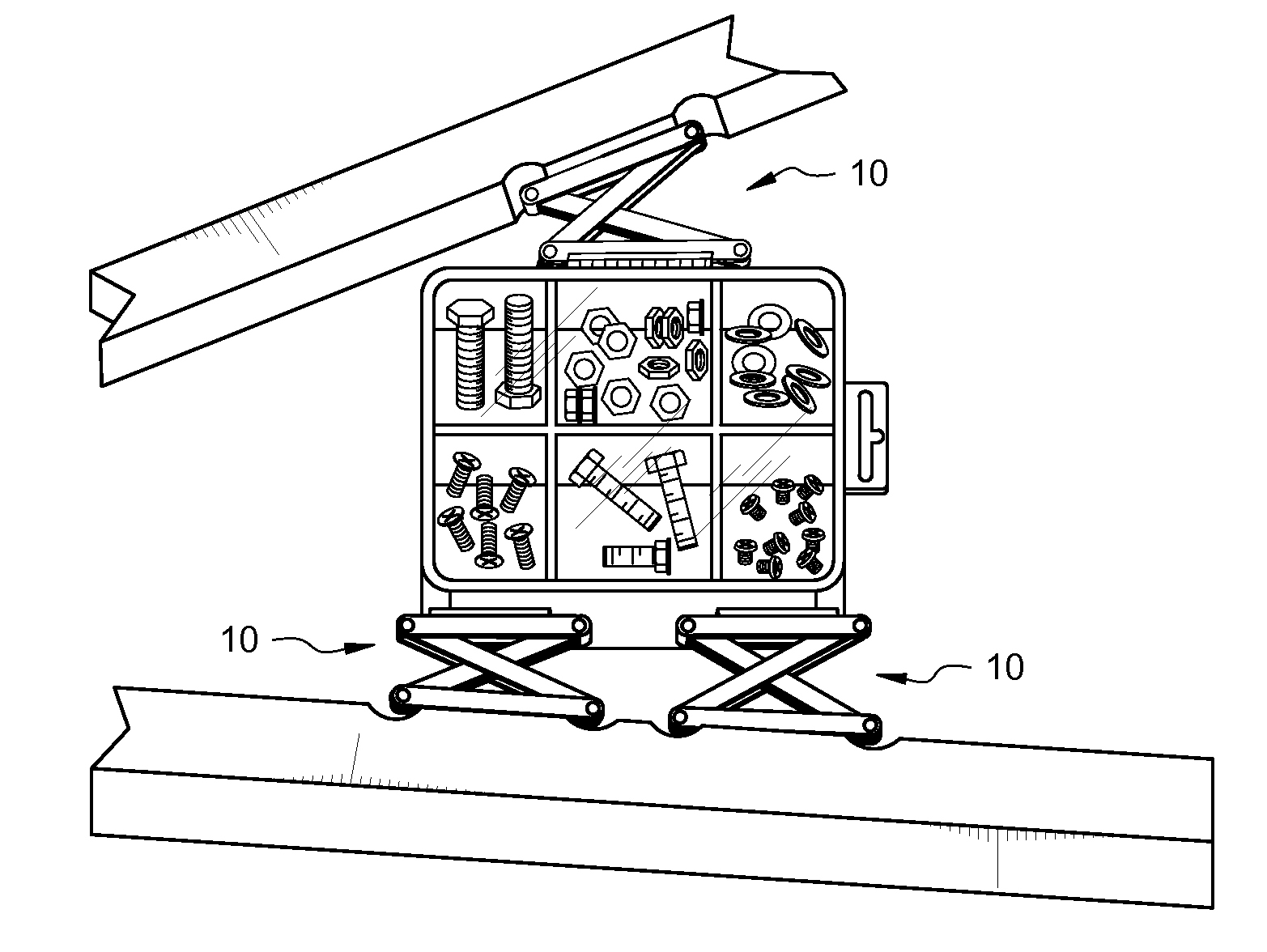
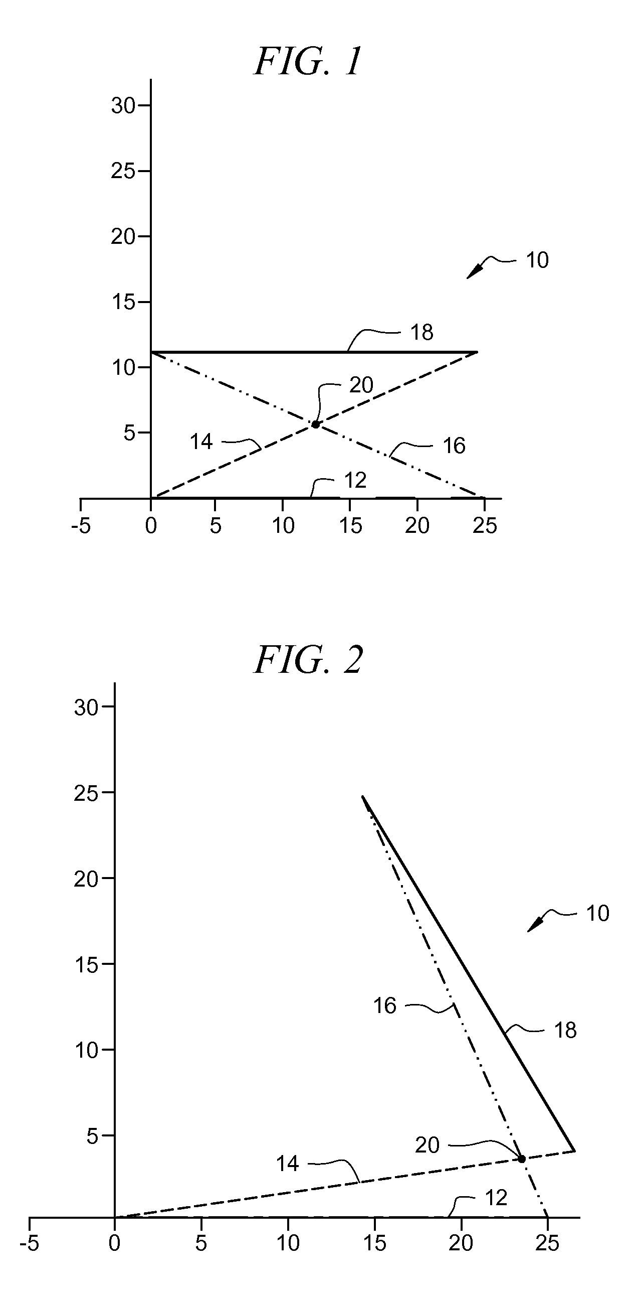
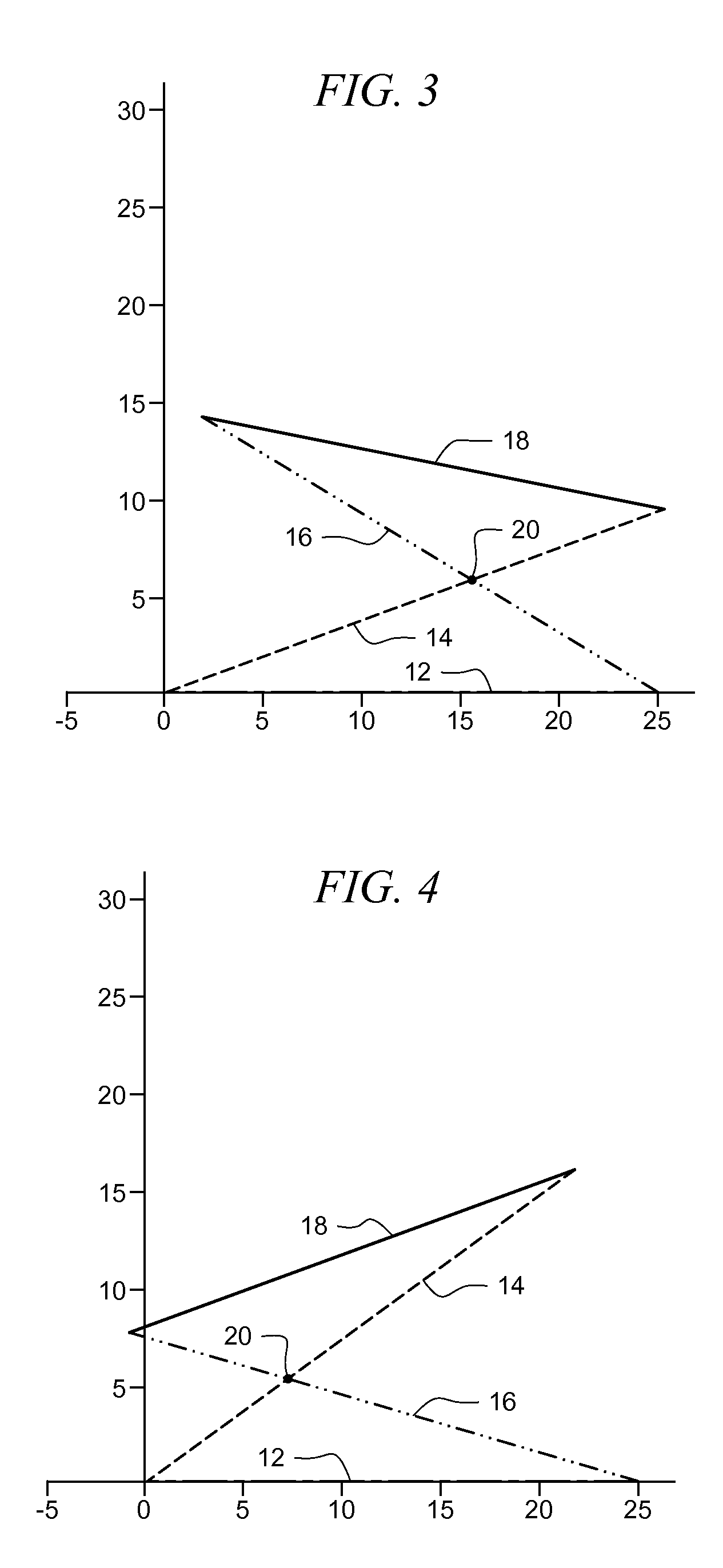
[0044]Referring now to FIG. 1, it will there be seen that the novel structure is denoted diagrammatically as a whole by the reference numeral 10. It includes a crossed four (4) bar linkage system having a base formed by base bar 12, two cross bars 14 and 16, and an interface bar 18. Base bar 12 is affixed to an artificial finger of an amputee. It may be adapted to be attached to various prosthetic devices for finger, hand, forearm, and transhumeral (arm) amputations.

[0045]Cross bar 14 has a first end pivotally mounted to a first end of base bar 12 and cross bar 16 has a first end pivotally mounted to a second end of said base bar 12. Cross bar 14 has a second end pivotally mounted to a first end of interface bar 18 and cross bar 16 has a second end pivotally mounted to a second end of said interface bar 18. The pivot points are defined by simple, uniplanar, hinge joints. In the simplest cases the finger may not have intermediate articulations.

[0046]Cross bars 14 and 16 are pivotally...


PUM


Abstract

A prosthetic finger includes a crossed four (4) bar linkage system having a base formed by a base bar, two cross bars, and an interface bar that engages an object to be held. The base bar is fixed to an artificial finger of an amputee. A first cross bar has a first end pivotally mounted to a first end of the base bar and a second cross bar has a first end pivotally mounted to a second end of the base bar. The first cross bar has a second end pivotally mounted to a first end of the interface bar and the second cross bar has a second end pivotally mounted to a second end of the interface bar. The first and second cross bars are slideably interconnected to one another at a cross point which changes its location as the prosthesis grasps objects of differing sizes and shapes.

Description

CROSS REFERENCE TO RELATED APPLICATION[0001]This application claims priority to currently pending U.S. Provisional Patent Application No. 60 / 864,066, entitled “Conforming Artificial Finger Mechanism for Prosthetic or Robotic Hands”, filed on Nov. 2, 2006, the contents of which are herein incorporated by reference.STATEMENT OF GOVERNMENT INTEREST[0002]This invention was made with U.S. government support under Grant No. 6140100000 awarded by the U.S. Department of Education / RSA. The government has certain rights in the invention.BACKGROUND OF THE INVENTION[0003]1. Field of the Invention[0004]This invention relates to prosthetics. More particularly, it relates to a non-anatomical artificial finger or fingertip that does not require complex control systems.[0005]2. Description of the Prior Art[0006]Most upper extremity amputations are the result of abnormal development, trauma, or medical treatment. Amputations of the hand result in chronic disability. Conventional designs of artificial...

Claims


Application Information

Patent Timeline
IPC IPC(8): A61F2/42
CPCA61F2/586A61F2/588A61F2002/7635A61F2/72A61F2002/6827A61F2/68Y10S294/902
Inventor MAITLAND, MURRAY E.HIGHSMITH, M. JASONLUSK, CRAIG
Owner UNIV OF SOUTH FLORIDA
Why Eureka
Try Eureka