
Power Theft Detection System and Method

a detection system and power theft technology, applied in the direction of electric devices, instruments, transportation and packaging, etc., can solve the problems of power theft, illegal tapping into the power line upstream of the power meter to supply power to a premises or a device, and approximately 3% of the power being generated in the united states is stolen, and the effect of power theft on consumers and society

Inactive Publication Date: 2008-05-08
CURRENT TECH
View PDF28 Cites 242 Cited by
  • Summary
  • Abstract
  • Description
  • Claims
  • Application Information

AI Technical Summary

Benefits of technology

"The present invention provides a device, system, and method for providing utility data services. The method involves receiving meter data of power consumed by multiple customers and delivered power data that includes power delivered to the customers. The difference between the meter data and the delivered power data is determined, and if the difference exceeds a predetermined amount, a discrepancy is indicated. The discrepancy may also be determined to be varying over time by a predetermined amount, and a notification of the discrepancy can be provided wirelessly or via power line. Overall, the invention allows for more accurate measurement and monitoring of power consumption and delivery."

Problems solved by technology

Tapping into the power line upstream of the power meter to supply power to a premises or devices is illegal and is power theft.
It is estimated that approximately 3% of the power being generated in the United States is stolen (used by, but not paid for, by consumers).
Other than the loss of revenue to the utility provider, power theft also has adverse effects on consumers and society.
As a result, the paying consumer ends up subsidizing the power thief by paying the thief's share of the power costs.
Therefore, the thief does not have the same motivation to conserve power, which, in the aggregate, may impact the environment.
One of the challenges in stopping power theft is the difficulty in detecting power theft.
In particular it is difficult to obtain data which identifies specific locations where power theft is occurring.
Measurement of such parameters has not been available in a satisfactory manner to optimize power network management.

Method used


Image

  • Power Theft Detection System and Method
  • Power Theft Detection System and Method
  • Power Theft Detection System and Method

Examples


Embodiment Construction

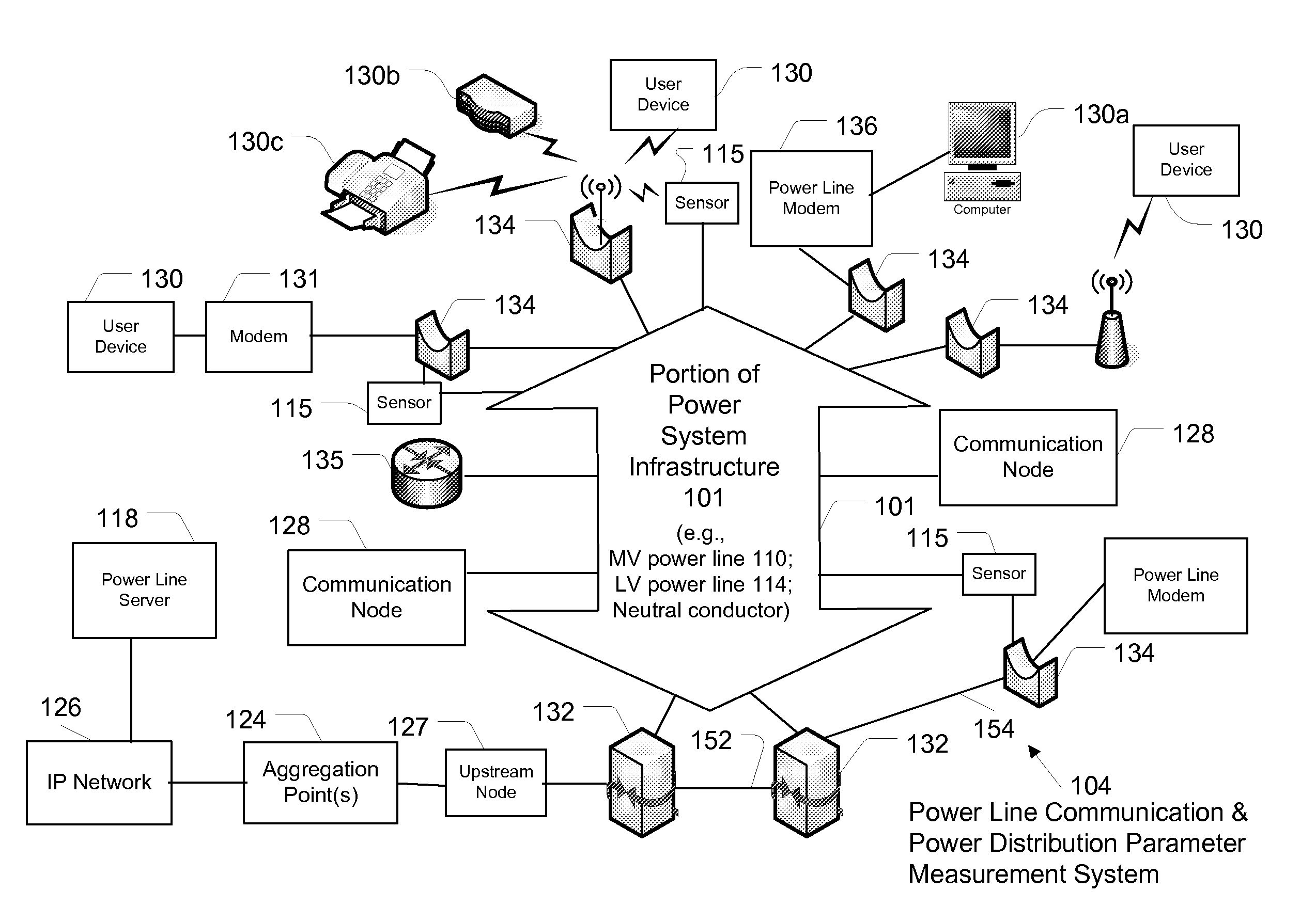
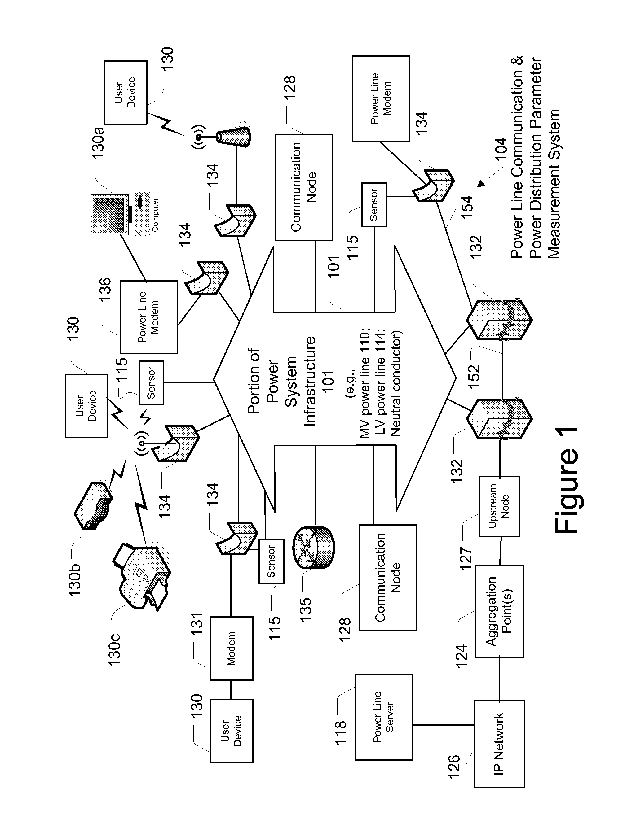
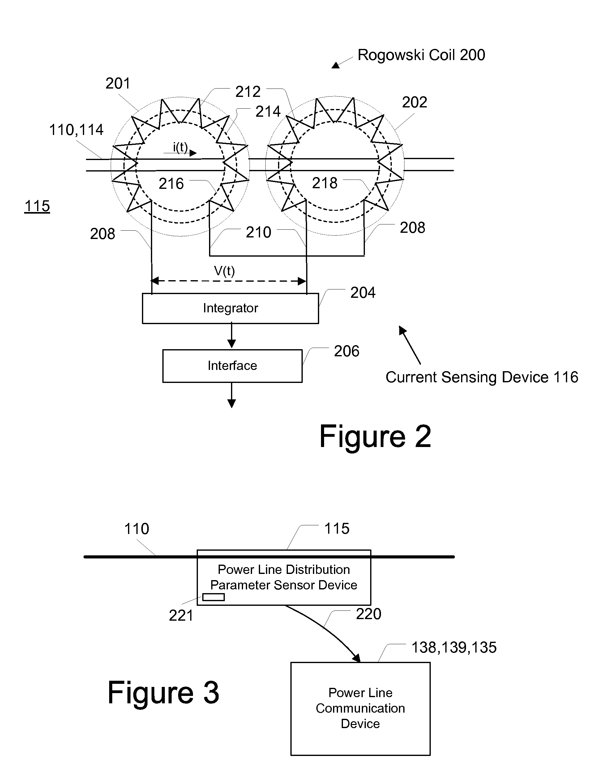
[0033]In the following description, for purposes of explanation and not limitation, specific details are set forth, such as particular networks, communication systems, computers, terminals, devices, components, techniques, data and network protocols, power line communication systems (PLCSs), sensor devices, software products and systems, enterprise applications, operating systems, development interfaces, hardware, etc. in order to provide a thorough understanding of the present invention.

[0034]However, it will be apparent to one skilled in the art that the present invention may be practiced in other embodiments that depart from these specific details. Detailed descriptions of well-known networks, communication systems, computers, terminals, devices, PLCSs, components, techniques, sensor devices, data and network protocols, software products and systems, operating systems, development interfaces, and hardware are omitted so as not to obscure the description of the present invention.

[...


PUM


Abstract

A system and method of providing utility data services is provided. In one embodiment the method includes receiving meter data of the measured power consumed by a plurality of power customers, receiving delivered power data that includes data of the power delivered to the plurality of power customers, determining a difference between the meter data and the delivered power data, determining that the difference between the meter data and the delivered power data is greater than a predetermined amount, and indicating a discrepancy if the difference between the meter data and the delivered power data is greater than a predetermined amount. In addition, the method may include determining that a discrepancy varies over time by a predetermined amount and providing a discrepancy notification such as wirelessly and / or via power line.

Description

CROSS REFERENCE TO RELATED APPLICATIONS[0001]This application is a continuation-in-part of, and claims priority to, U.S. patent application Ser. No. 11 / 555,740 filed Nov. 2, 2006 (CRNT-0302-US), which is incorporated herein by reference in its entirety.FIELD OF THE INVENTION[0002]The present invention generally relates to methods and apparatus for detecting power theft, and more particularly to methods and apparatus for detecting, locating, and communicating power theft in a power distribution system.BACKGROUND OF THE INVENTION[0003]Electrical power for consumption at residences, offices and other structures is delivered by a power distribution system. Electrical power is transmitted at high voltages from a power plant to substations near populated areas. Electrical power then is distributed from a substation along power lines and through distribution transformers toward consumer premises. Utility meters typically are located at the consumer's premises to measure the amount of power...

Claims


Application Information

Patent Timeline
Patent Type & Authority Applications(United States)
IPC IPC(8): G06Q99/00G01R11/00
CPCG01R19/16547G06Q50/06G01R19/2513
Inventor DEAVER, BRIAN J.RADTKE, WILLIAM O.
Owner CURRENT TECH
Learn More