Imaging device
a technology of imaging device and image, applied in the field of imaging device, can solve problems such as image deterioration of synthetic images, and achieve the effect of improving the image quality of synthetic images
- Summary
- Abstract
- Description
- Claims
- Application Information
AI Technical Summary
Benefits of technology
Problems solved by technology
Method used
Image
Examples
first embodiment
[0071]In the first embodiment, N is a positive integer greater than a positive integer M. For example, the value of N is a value obtained by adding a predetermined natural number to M.
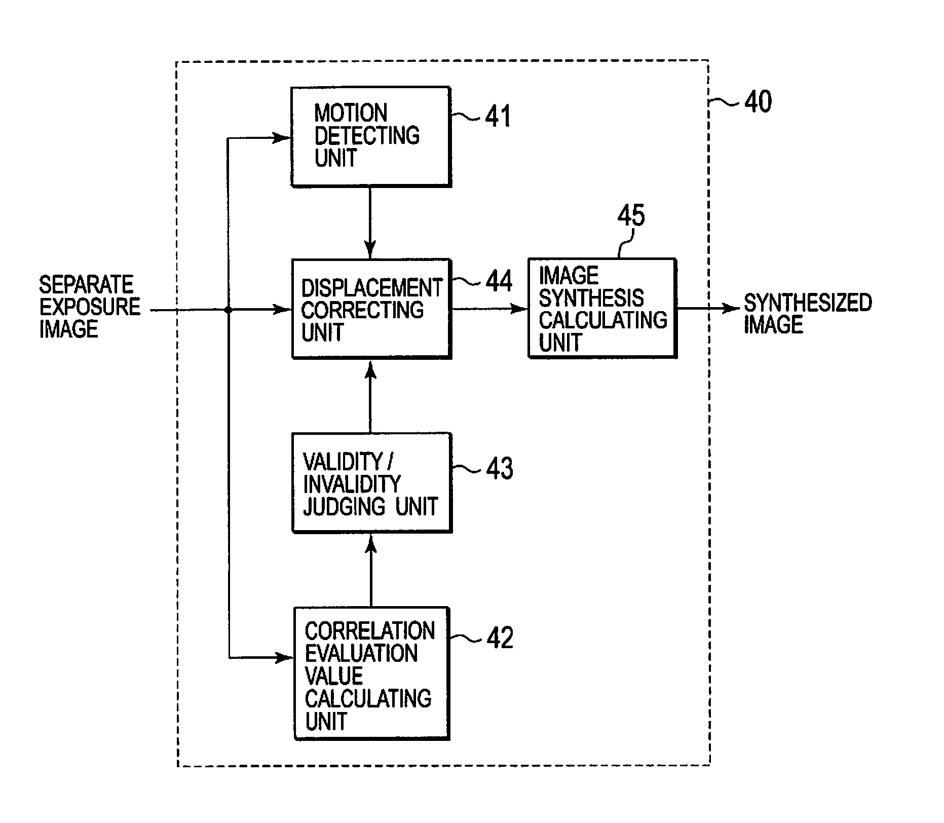
[0072]In the first embodiment, a first processing procedure is adopted as a processing procedure for an additive synthesis. FIGS. 5A and 5B are conceptual diagrams of the first processing procedure. In the first embodiment, all of N separately-exposed images acquired by serial capturing are temporarily stored in an image memory 50 as shown in FIG. 5A. For this image memory 50, the SDRAM 17 of FIG. 1 is used, for example.
[0073]Further, among the N separately-exposed images, one of the N separately-exposed images is determined to be a reference image Io, and (N−1) separately-exposed images other than the reference image are set as non-reference images In (n=1, 2, . . . , (N−1)). A way of determining which separately-exposed image will become the reference image Io will be described later. Hereinafter, fo...
second embodiment
[0099]Next, a second embodiment will be described. In the second embodiment, the second processing procedure is adopted as a processing procedure for additive synthesis.
[0100]FIG. 9 is a conceptual diagram showing the second processing procedure. In the second processing procedure, among N separately-exposed images which are serially captured, a separately-exposed image which is shot first is set as a reference image Io, and separately-exposed images which are shot subsequent to the first one are set as non-reference images In. The reference image Io is stored in the image memory 50.
[0101]Thereafter, each time when a separately-exposed image is newly captured subsequent to the first shot, the strength of a correlation between one non-reference image In newly captured and the reference image Io is evaluated, and it is judged whether the one non-reference image In is valid or invalid. The processing involved in this judgment is the same as that of Step S3, and Steps S5 to S8 (FIG. 6) ...
third embodiment
[0110]Next, a third embodiment illustrates a method of evaluating the strength of correlation. The third embodiment is achieved in combination with the first and second embodiments.
[0111]As methods of evaluating the strength of correlation, first to fifteenth evaluation methods will be exemplified. In the description of each evaluation method, a method of calculating a correlation evaluation value will also be described.
[0112]In the first, third, fifth, seventh, ninth, eleventh, and thirteenth evaluation methods, as shown in FIG. 11, one correlation evaluation region is defined within each separately-exposed image. In FIG. 11, reference numeral 201 designates one separately-exposed image, and reference numeral 202 designates one correlation evaluation region defined within the separately-exposed image 201. The correlation evaluation region 202 is, for example, defined as the entire region of the separately-exposed image 201. Incidentally, it is also possible to define, as the correl...
PUM
 Abstract
Description
Claims
Application Information
 - R&D
- Intellectual Property
- Life Sciences
- Materials
- Tech Scout
- Unparalleled Data Quality
- Higher Quality Content
- 60% Fewer Hallucinations
Browse by: Latest US Patents, China's latest patents, Technical Efficacy Thesaurus, Application Domain, Technology Topic, Popular Technical Reports.
© 2025 PatSnap. All rights reserved.Legal|Privacy policy|Modern Slavery Act Transparency Statement|Sitemap|About US| Contact US: help@patsnap.com


