Microbial resistant vehicle air conditioning ductwork

US20080113602A1Inactive Publication Date: 2008-05-15AIR INT
7 Cites 3 Cited by

Patent Information

Authority / Receiving Office
US · United States
Current Assignee / Owner
Publication Date
2008-05-15
Estimated Expiration
Not applicable · inactive patent

Smart Images

  • Figure 1
    Figure 1
  • Figure 2
    Figure 2
  • Figure 3
    Figure 3
Patent Text Reader

Abstract

A vehicle HVAC system includes a HVAC components such as a duct, vent, manually adjustable airflow control head, toggle or housing manufactured from a molded plastic material having an antimicrobial additive. The antimicrobial additive is preferably introduced as an additive during molding of the HVAC components that are typically injection or blow molded parts. Usage of a plastic having an antimicrobial additive continuously fights the growth of microbes such as most common bacteria, yeasts, molds and fungi that cause stains, odors and product degradation that can cause stains, odors and product degradation. The antimicrobial additive becomes an integral part of the HVAC components and therefore is maintenance free.
Need to check novelty before this filing date? Find Prior Art

Description

BACKGROUND OF THE INVENTION

[0001] The present invention relates to a vehicle air conditioning system, and more particularly to microbial resistant vehicle air conditioning duct work.

[0002] Vehicle air conditioning systems are provided in most vehicles to maintain the passenger compartment of the vehicle at an acceptable temperature. In general, vehicle air conditioning systems include a compressor coupled to the engine that compresses a refrigerant to its liquid state. The compressed liquid refrigerant is then delivered to a heat exchanger within the air conditioning system, where it is allowed to expand and cool the exchanger. A blower forces air across the heat exchanger and into the passenger compartment of the vehicle. As the air passes through the cold heat exchanger, it is cooled and the latent heat that was contained in the air is transferred to the refrigerant within the heat exchanger. Thus, the passenger compartment receives cool air. The heated refrigerant is then passed th...

Examples

Embodiment Construction

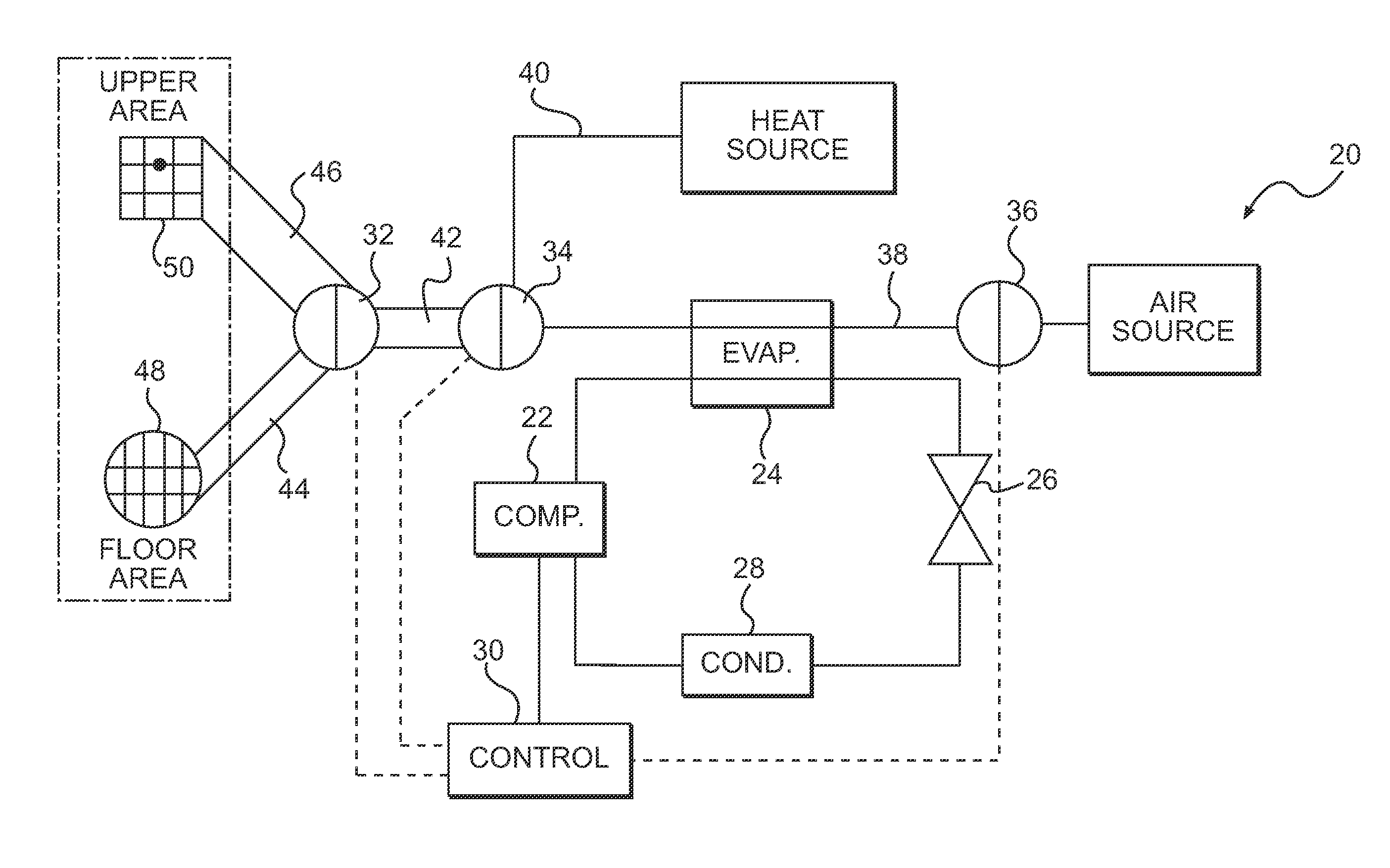
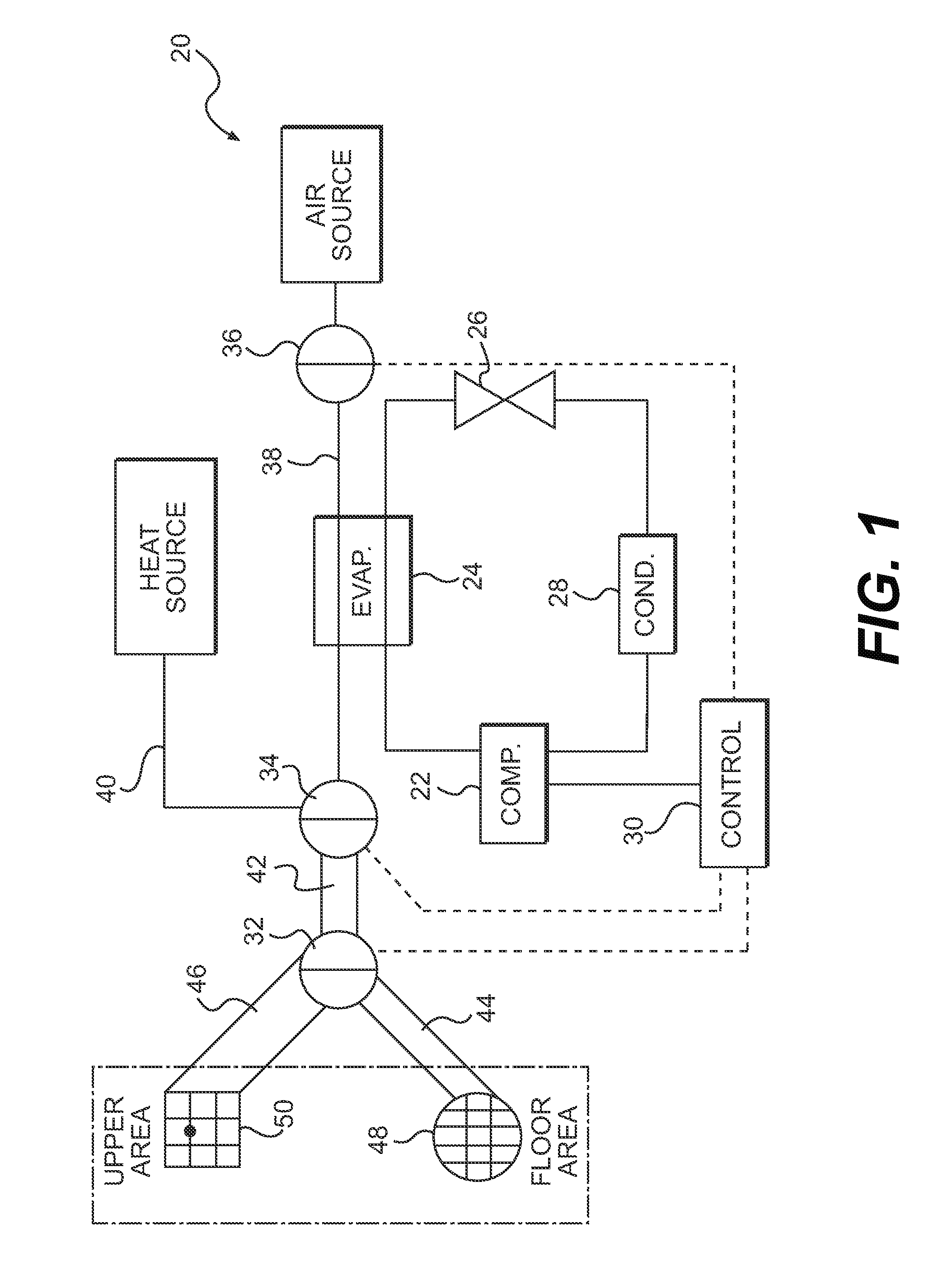
[0013]FIG. 1 schematically illustrates a portion of a vehicle HVAC system 20. As generally understood, the system 20 includes a refrigerant circuit having a compressor 22, an evaporator 24, an expansion element 26 and a condenser 28. An electronic control 30 controls the operation of at least the compressor and various fans associated with the HVAC system 20.

[0014]The HVAC system 20 includes system flow control doors 32, 34 and 36 which are preferably controlled by the control 30. The airflow flow into the vehicle passenger compartment through at least two supply channels 38, 40. As shown, supply channel 38 passes through the evaporator 24, and thus is a source of cool air. Supply channel 40 communicates from a heat source such as that generally known in vehicle HVAC systems. The two channels 38, 40 mix to reach a downstream duct 42. The door 34 controls the mixing of flow between the channels 38, 40.

[0015]Once the conditioned air reaches duct 42, it is at a generally desired temper...