Coating, coating layer system, coated superalloy component

a superalloy and coating layer technology, applied in the direction of superimposed coating process, machines/engines, transportation and packaging, etc., can solve the problems of increasing the price of coatings, reducing limiting the effort of temperature capacity, so as to improve the oxidation resistance of superalloy components, the effect of increasing the temperature capacity

Active Publication Date: 2016-03-01
SIEMENS ENERGY GLOBAL GMBH & CO KG
View PDF8 Cites 0 Cited by
  • Summary
  • Abstract
  • Description
  • Claims
  • Application Information

AI Technical Summary

Benefits of technology

[0010]It is one task of the invention to optimize the coating constitution, in order to achieve a good thermal stability of coating phase structures and a high mechanical durability.
[0011]It is another task to optimize the content and combination of the rare earth and minor elements in coatings, in order to minimize growths of oxides on top of the coating and interdiffusion between coating and superalloy substrates which lead to a rapid consumption of the Al reservoir in coatings thereby coating lifetime.
[0012]It is still another task of the invention to avoid the implementation of sulfur in the coating system shortening the coating lifetime.

Problems solved by technology

When further increasing engine efficiency, output power, availability and reliability in the current gas turbine development, this effort is often limited by temperature capacity and lifetime of protective coatings for protection against hot corrosion and oxidation and bonding thermal barrier coating on the hot turbine components.
Most gas turbine manufactures use there proprietary coatings since commercially available coatings are much less effective.
During the last ten years the demand for coatings in gas turbines increased, which led to an increase in price of the coatings, which contain comparatively large amounts of rare earth or minor elements which's availability is increasingly tight.
However, it has been recently found that the yttrium content in MCrAlY may not be optimized.

Method used


Image

  • Coating, coating layer system, coated superalloy component
  • Coating, coating layer system, coated superalloy component

Examples


Embodiment Construction

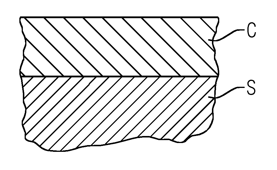
[0023]FIG. 1 shows a substrate as covered with an adherent coating C embodying aspects of the present invention as described below. The coating C is applied on a substrate by way of thermal spraying in air or vacuum or protected atmosphere or by way of physical vapor deposition or by way of plating. The substrate is part of a superalloy gas turbine component, for example a gas turbine vane or a gas turbine blade or a combustor part.

[0024]A cobalt based coating may comprise: 15 to 40 wt % nickel, 15 to 28 wt % chromium, 5 to 15 wt % aluminum, 0.05 to 1 wt % yttrium and / or at least one element from lanthanum series, 0.05 to 8 wt % ruthenium and / or molybdenum, 0 to 2 wt % iridium, 0 to 3 wt % silicon, 0 to 5 wt % tantalum, 0 to 2 wt % hafnium, unavoidable impurities, and a balance of cobalt.

[0025]In one embodiment the coating may contain 0.1 to 0.6 weight percent of silicon; in another embodiment the coating may contain 0.3 to 0.7 weight percent of tantalum; and in yet another embodime...


PUM

PropertyMeasurementUnit
weight percentaaaaaaaaaa
thicknessaaaaaaaaaa

Abstract

Coatings as may be used in a gas turbine are provided. A cobalt based coating may include 15 to 40 wt % nickel, 15 to 28 wt % chromium, 5 to 15 wt % aluminum, 0.05 to 1 wt % yttrium and / or at least one of elements from lanthanum series, 0.05 to 5 wt % ruthenium and / or molybdenum, 0 to 2 wt % iridium, 0 to 3 wt % silicon, 0 to 5 wt % tantalum, hafnium, unavoidable impurities, and a balance of cobalt. A nickel based coating may include 15 to 40 wt % cobalt, 10 to 25 wt % chromium, 5 to 15 wt % aluminum, 0.05 to 1 wt % yttrium and / or at least one of elements from lanthanum series, 0.05 to 8 wt % ruthenium or iron, 0 to 1 wt % iridium, 0.05 to 5 wt % molybdenum, 0 to 3 wt % silicon, 0 to 5 wt % tantalum, 0 to 2 wt % hafnium, unavoidable impurities, and a balance of nickel.

Description

CROSS REFERENCE TO RELATED APPLICATIONS[0001]This application is the US National Stage of International Application No. PCT / EP2012 / 068303 filed Sep. 18, 2012, and claims the benefit thereof. The International Application claims the benefit of European Application No. EP 11185990 filed Oct. 20, 2011. All of the applications are incorporated by reference herein in their entirety.FIELD OF INVENTION[0002]The invention relates to a coating, a coating layer system and a coated superalloy component preferably to be used in a gas turbine's hot gas path.BACKGROUND OF INVENTION[0003]When further increasing engine efficiency, output power, availability and reliability in the current gas turbine development, this effort is often limited by temperature capacity and lifetime of protective coatings for protection against hot corrosion and oxidation and bonding thermal barrier coating on the hot turbine components. The currently used coatings are so called MCrAlY coatings developed by major gas tur...

Claims


Application Information

Patent Timeline
Patent Type & Authority Patents(United States)
IPC IPC(8): C23C30/00C23C28/00C22C19/03C22C19/00B32B15/20B32B15/04C22C19/07C22C30/00C22C19/05F01D5/28F01D25/00
CPCF01D25/005C22C19/00C22C19/03C22C19/055C22C19/056C22C19/07C22C30/00C23C28/3215C23C28/345C23C28/3455C23C30/00F01D5/288Y10T428/12Y10T428/12611Y10T428/12618Y10T428/12861Y10T428/12931Y10T428/12937Y10T428/12944Y10T428/12979Y10T428/264Y10T428/265B32B15/04C23C28/022C23C28/00Y10T428/1266Y10T428/12667Y02T50/60
Inventor LI, XIN-HAI
Owner SIEMENS ENERGY GLOBAL GMBH & CO KG
Why Eureka
Try Eureka