Eureka AIR delivers breakthrough ideas for toughest innovation challenges, trusted by R&D personnel around the world.

Circulation System for a Ball Screw

Inactive Publication Date: 2008-05-22
HIWIN TECH
View PDF7 Cites 11 Cited by
  • Summary
  • Abstract
  • Description
  • Claims
  • Application Information

AI Technical Summary

Benefits of technology

[0012]The primary objective of the present invention is to provide a circulation system for a ball screw, and more particularly to a circulation system, wherein a positioning groove of the nut is axially formed with an abutting surface having a tapered a hole for mating with a turning structure of the return assembly such that the positioning groove doesn't destroy the helical groove while not interfering with the helical groove, further, the radius of curvature of the return path can be increased, and thus improving the ease of rolling of the balls during circulation.
[0014]By such arrangements, the design of the return assembly of the present invention can solve the problem that the radius of curvature of the conventional return path is relatively small and the positioning groove destroys the helical groove, thus increasing the radius of curvature of the return path, and relatively improving the ease of rolling of the balls during circulation.

Problems solved by technology

For the design of this return assembly 10, the lead of the ball screw cannot be too short, otherwise the tip of the next thread will be damaged due to the lead is too short and the tip of thread is too small.
However, since the return assembly 20 with the compensating portion 201 can only be separated into two parts 202 and 203, and the return path of the return assembly 20 for enabling the balls to make a return is limited and still cannot be designed to be too large.
If the return path is too small, the balls cannot roll smoothly through it.
Inevitably, the motion of the balls with respect to the screw and the nut will be adversely affected, resulting in a decrease in the mechanical efficiency of the ball screw.

Method used


Image

  • Circulation System for a Ball Screw
  • Circulation System for a Ball Screw
  • Circulation System for a Ball Screw

Examples


Embodiment Construction

[0029]The present invention will be more clear from the following description when viewed together with the accompanying drawings, which show, for purpose of illustrations only, the preferred embodiment in accordance with the present invention.

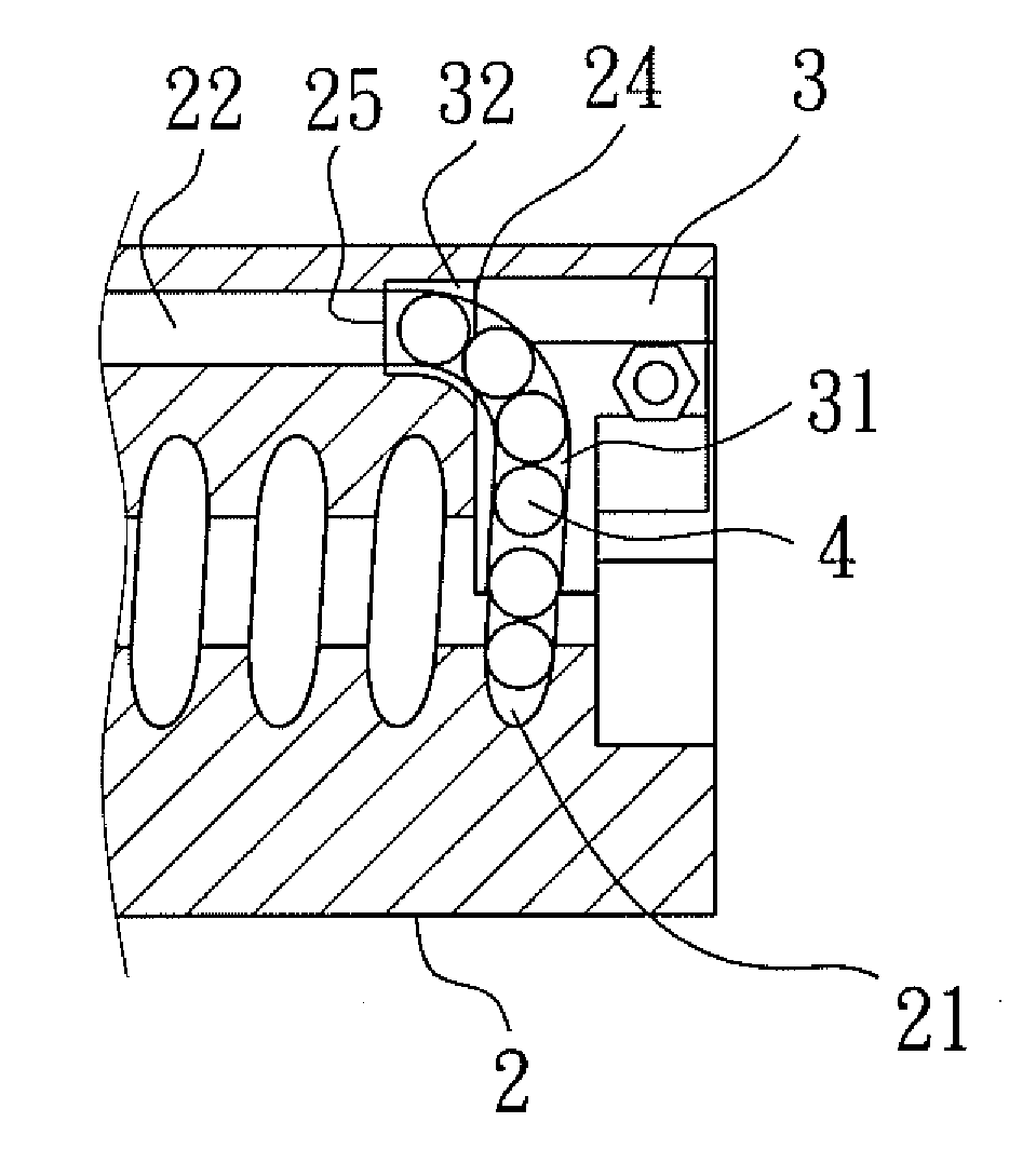
[0030]Referring to FIGS. 5-10, a circulation system for a ball screw in accordance with the present invention is illustrated and comprises: a screw 1, a nut 2, a plurality of return assemblies 3 and balls 4. In the outer surface of the screw 1 is formed a helical groove 11 for mating with a helical groove 21 formed in the inner surface of the nut 2. At least one through hole 22 is defined in the nut 2 and has at least one positioning groove 23 formed in either end surface of the nut 2 for insertion of the return assemblies 3. In each of the return assemblies 3 are defined a return path 31 and two open ends 311, 312, and the two open ends 311, 312 are connected to the through hole 22 and the helical groove 21 of the nut 2, respectively. The hel...


PUM


Abstract

A circulation system for a ball screw comprises: a screw, a nut, a plurality of return assemblies and balls. The positioning groove of the nut is axially formed with an abutting surface for mating with the return assemblies, in the abutting surface is formed a tapered hole for connecting the through hole, and the abutting surface doesn't interfere with the helical groove, on the open end of the returning assemblies connecting to the through hole is formed a protruding turning structure to be engaged in the tapered hole. The design of the return assembly of the present invention can solve the problem that the radius of curvature of the conventional return path is relatively small and the positioning groove destroys the helical groove, thus increasing the radius of curvature of the return path, and relatively improving the ease of rolling of the balls during circulation.

Description

BACKGROUND OF THE INVENTION[0001]1. Field of the Invention[0002]The present invention relates to a circulation system for a ball screw, and more particularly to a circulation system, wherein a positioning groove of the nut is axially formed with an abutting surface having a tapered a hole for mating with a turning structure of the return assembly, so that the positioning groove can avoid and doesn't interfere with the helical groove, meanwhile, the radius of curvature of the return path can be increased.[0003]2. Description of the Prior Art[0004]Ball screw is such a mechanism that its nut is mounted onto a screw, and then a plurality of balls circulate between the screw and the nut to produce relative motion.[0005]To enable the balls in a circulation space between the screw and the nut to make a turn, a return assembly should be disposed in the inner threads of the nut, so that the balls can make a turn and circulate endlessly.[0006]Currently, the existing methods for enabling circu...

Claims


Application Information

Patent Timeline
IPC IPC(8): F16H25/22
CPCY10T74/19772F16H25/2219
Inventor TSOU, CHIEN-WEIWU, WEN-CHIA
Owner HIWIN TECH
Why Eureka
Eureka Blog
Learn More