Brake Device and Controller for The Same

a technology of brake device and controller, which is applied in the direction of braking system, braking components, transportation and packaging, etc., can solve the problems of deteriorating pedaling feeling of the driver, affecting the pedaling experience of the driver, and the inability to control the plurality of brake forces independently from each other, so as to achieve satisfactory pedal feeling

Active Publication Date: 2008-05-22
HITACHI ASTEMO LTD
View PDF8 Cites 23 Cited by
  • Summary
  • Abstract
  • Description
  • Claims
  • Application Information

AI Technical Summary

Benefits of technology

[0007]An object of the present invention is to provide a brake system for assisting a pedal force by a driver with the use of a small-sized electric actuator, having satisfactory pedaling feeling, and as well to provide a control apparatus for a brake system.
[0023]An embodiment of the present invention is composed of a first brake actuator for increasing the hydraulic pressure of the master cylinder by a drive torque of an electric motor in order to assist the pedaling force by the driver, and a second brake actuator capable of driving the brake force generating mechanism without feeding power to the master cylinder. Thus, a pedaling force can be assisted by the electric actuator upon weak braking while the second brake actuator can apply a brake force to wheels without the hydraulic pressure in the master cylinder being changed, thereby it is possible to provide a brake system having satisfactory pedal feeling, capable of assisting a pedaling force of the driver by means of a small-sized electric actuator.
[0025]The second brake actuator comprises a hydraulic valve between the master cylinder and the hydraulic pump, and the hydraulic valve is shut off when the second brake actuator is operated, so as to achieve the object of the present invention. Thus, no variation in hydraulic pressure is caused when the hydraulic actuator is operated, and thereby it is possible to constitute a brake system having satisfactory pedal feeling, capable of assisting a pedaling force of the driver by means of a small-sized electric actuator.
[0027]The drive of the above-mentioned second brake actuator is started in accordance with a degree of a signal from a pedal sensor for detecting a displacement or a pedaling force of the brake pedal or in accordance with a time when the signal value from the pedal sensor is not less than a predetermined value, so as achieve the object of the present invention. Thus, even though the small-sized electric actuator is used, the operation frequency of the hydraulic actuator can be limited, and a restoring force of a resilient member does not cause any burden upon the drive unit when the stiffness is adjusted at an initial position, thereby, it is possible to constitute a brake system having satisfactory pedal feeling, capable of assisting a pedaling force of the driver by means of a small-sized electric actuator.
[0028]The first brake actuator drives a brake force generating mechanism for at lease one of a plurality of wheels incorporated in the vehicle, and the second brake actuator drives a brake force generating mechanism different from that driven by the first brake actuator, so as to achieve the object of the present invention. Thus, the assist force which should be generated by the electric actuator can be reduced, thereby it is possible to constitute a brake system capable of assisting a pedaling force of the driver by means of a small-sized electric actuator.
[0039]As stated above, according to the present invention, there are provided the electric actuator for increasing the hydraulic pressure of the master cylinder by means of the drive torque of the electric motor, and the second actuator which can drive the brake force generating mechanism without transmitting a power to the master cylinder in order to change over the actuators to be driven in accordance with an operating condition of the brake pedal. Thereby it is possible to provide a brake system having satisfactory pedal feeling, capable of assisting a pedaling force of the driver by a small-sized electric motor and of individually controlling braking forces for a plurality of wheels, and the control apparatus therefor.

Problems solved by technology

Accordingly, there has been raised such a problem that the electric brake boosting mechanism becomes inevitably large-sized in order to materialize an electric brake boosting mechanism having a drive capacity substantially equal to that of the vacuum type brake boosting mechanism.
Also in the example disclosed in JP-A-10-35438, since a brake pedal is not mechanically isolated from a strong brake actuator, should a heavy brake actuator be driven in order to assist the operation by the driver, there would be caused such a problem that the pedaling feeling for the driver is deteriorated.
Further, since both electric actuator and heavy brake actuator are coupled with the brake pedal, a plurality of brake forces cannot be controlled independently from each other even though two actuators are present.

Method used


Image

  • Brake Device and Controller for The Same
  • Brake Device and Controller for The Same
  • Brake Device and Controller for The Same

Examples


embodiments

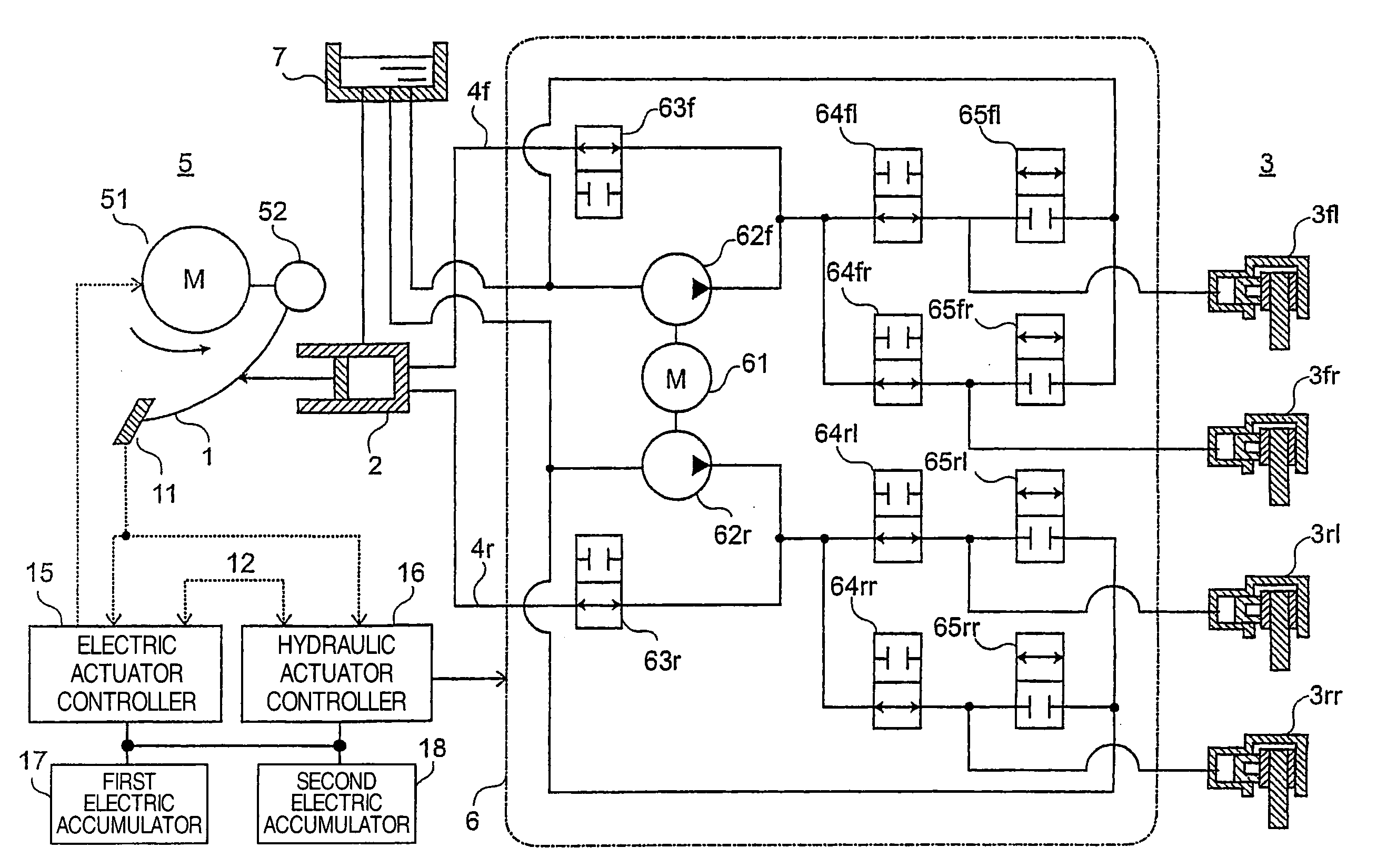
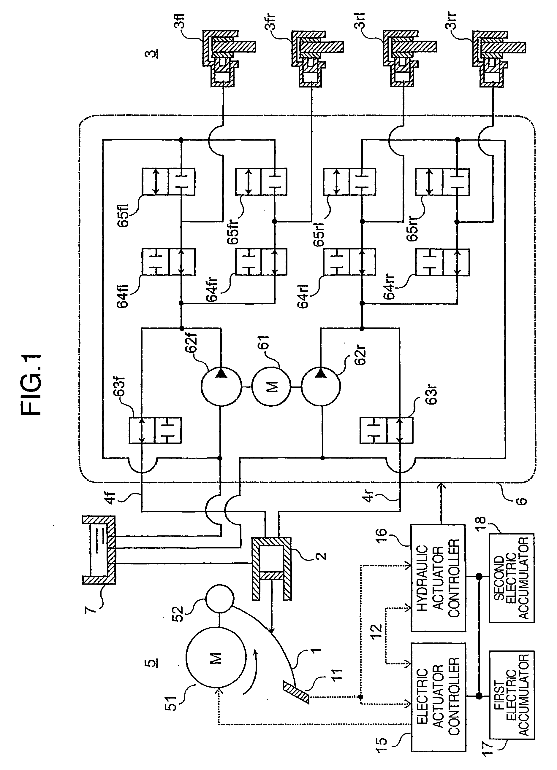
[0045]FIG. 1 shows a first embodiment of the present invention. In the foregoing description, it is noted that suffixes f and r of reference numerals will indicate front wheels and rear wheels, respectively, and suffixes fl and fr indicate front left and front right wheels, respectively while suffixes rl and rr indicate rear left and rear right wheels, respectively. Reference numerals without suffix will indicate all of the wheels.

[0046]A brake system is composed of a brake pedal 1 which is applied thereto with a pedaling force applied when the driver desires deceleration of a vehicle, and which is displaced in response to the pedaling force, a master cylinder 2 for converting a pedaling force at the brake pedal 1 into a pressure of brake fluid, brake force generating mechanisms (devices) 3fl-3rr for converting a hydraulic pressure from the master cylinder 2 into brake forces for four wheels, hydraulic pipe lines 4f, 4r connecting the master cylinder 2 to the brake force generating ...


PUM


Abstract

A brake system that provides a good pedal feel, that assists stepping force of a driver by a small motor, and that can control braking force of wheels individually. The brake system comprises a first actuator (5) for increasing a liquid pressure in a master cylinder (2) by driving torque of a motor (51), and a second actuator (6) capable of driving a brake generating mechanism (3) without transmitting power to the master cylinder (2), wherein the actuators (5, 6) to be driven are switched depending on the operation of a brake pedal (1). The first and second actuators (5, 6) are connected to hydraulic piping (4f, 4r), and a pressurized oil is supplied to the brake generating mechanism (3) through hydraulic valve means (63f, 63r, . . . 65rr).

Description

TECHNICAL FIELD[0001]The present invention relates to a brake system for an automobile, and in particular to an electronic control apparatus in a brake system for driving and controlling a brake force under electronic control.BACKGROUND ARTBackground Art[0002]In general, a brake system for a vehicle comprises a master cylinder for converting a pedaling force applied to a brake pedal by an operator into a hydraulic pressure of brake fluid, brake force generating mechanisms provided in the vehicle, and composed of friction discs and the like, a brake transmission mechanism for transmitting a hydraulic pressure from the master cylinder to the brake force generating mechanism, and a vacuum type boosting mechanism for pressurizing the brake fluid in the master cylinder in cooperation with the pedaling force of the operator, so as to assist the pedaling force of the operator. By the way, those using the vacuum type boosting mechanism utilize an engine vacuum as a pressure source, and acco...

Claims


Application Information

Patent Timeline
Patent Type & Authority Applications(United States)
IPC IPC(8): B60T8/00
CPCB60T7/042B60T8/267B60T8/321B60T13/745B60T8/4872B60T8/94B60T13/161B60T8/442
Inventor YOKOYAMA, ATSUSHITANIMICHI, TAISETSUKURAGAKI, SATORUOSAWA, YUKIHIROKUBO, JUNINOUE, YUKIHIKOIWASAKI, KATSUYASASAKI, MITSUOHIBI, TSUTOMU
Owner HITACHI ASTEMO LTD
Why Eureka
Try Eureka