
System for preparing bone for receiving an implant

a bone implant and bone technology, applied in the field of surgical tools and procedures, can solve the problems of not being able to precisely define the cut line through bone, not being able to see and cut the lines of conventional saws and cutting guides, and noticeable limitations

Inactive Publication Date: 2008-05-22
HOWMEDICA OSTEONICS CORP
View PDF23 Cites 51 Cited by
  • Summary
  • Abstract
  • Description
  • Claims
  • Application Information

AI Technical Summary

Benefits of technology

[0019]These and other preferred embodiments of the pre

Problems solved by technology

Conventional saws and cutting guides work reasonably well, however, there are some noticeable limitations.
This repetitive contact wears away the slot-defining material, which widens the slot so much that it can no longer serve to precisely define cut lines through bone.
Another disadvantage of the cutting blade engaging the side walls of the slot is that the extra power required to overcome friction forces will reduce the life of the battery powering the saw.
In addition, the wearing of the material defining the slots of the cutting guide generates a fine dust that settles at the surgical site.
Having to repeatedly perform this flushing process will also lengthen the surgical procedure and the amount of time the patient is subject to anesthesia.
Furthermore, the oscillating motion of the blade causes vibration of the saw.
As a result, the surgeon is required to engage in some conscious or unconscious physical effort to hold the saw steady when it vibrates.
Over time, having to hold the saw steady to overcome this vibration can be mentally and physically draining.
As a result, the oscillating saw blade used in a bone resection procedure is typically longer than the saw blade used to perform a conventional resection.
This increased vibration can make it difficult for a surgeon to hold the saw steady.
Moreover, a longer blade is more flexible than a shorter blade, which can result in the longer blade making less precise cuts in the bone.

Method used


Image

  • System for preparing bone for receiving an implant
  • System for preparing bone for receiving an implant
  • System for preparing bone for receiving an implant

Examples


Embodiment Construction

[0035]In the present application, certain terminology is used for describing the invention and should not be construed as limiting the scope of the invention. For example, the words “upwardly”, “downwardly”, “rightwardly” and “leftwardly” will refer to directions in the drawings to which reference is made. The words “inwardly” and “outwardly” refer to directions toward and away from, respectively, the geometric center of what is shown in the drawings. The word “distally” means the end of a tool that is closer to a patient, and the word “proximally” means the end of the tool that is further away from the patient. The above terminology includes the words specifically mentioned, derivatives thereof, and words of similar import.

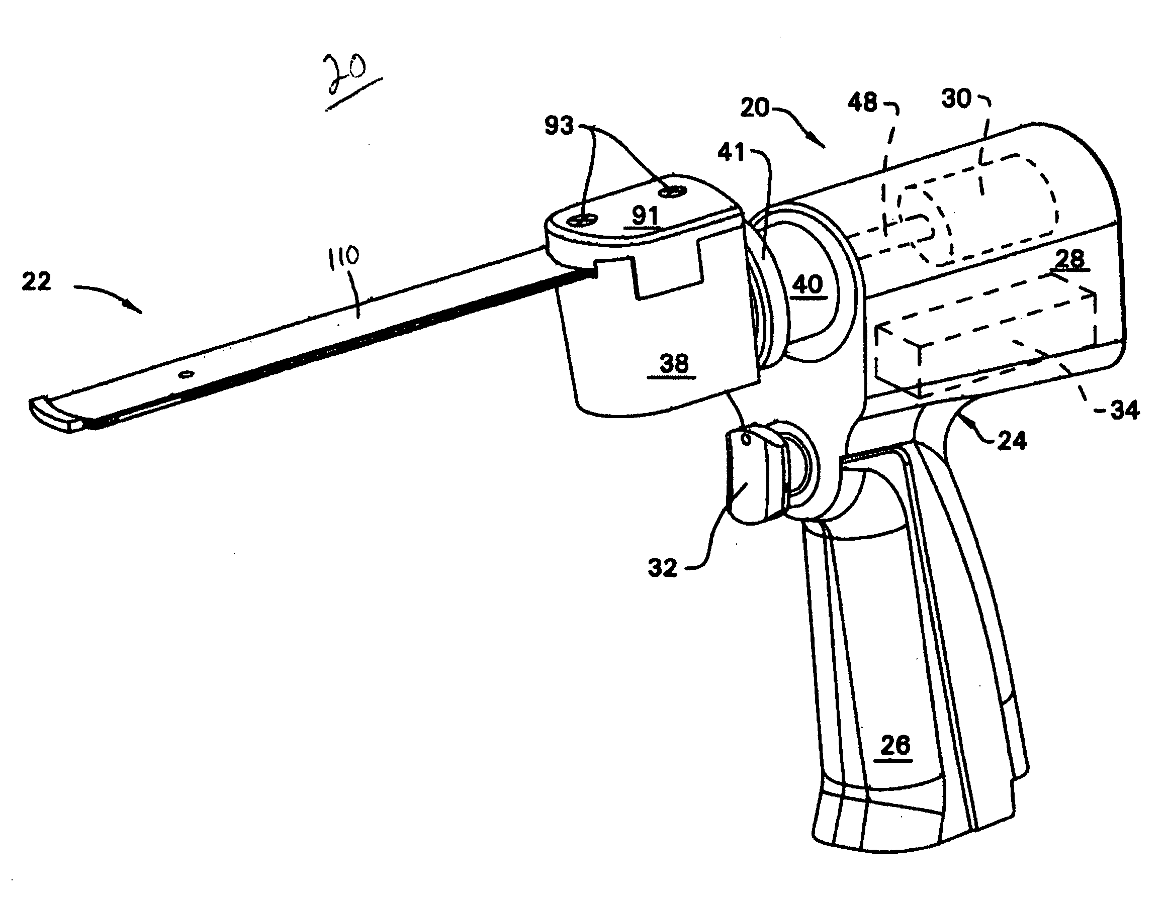
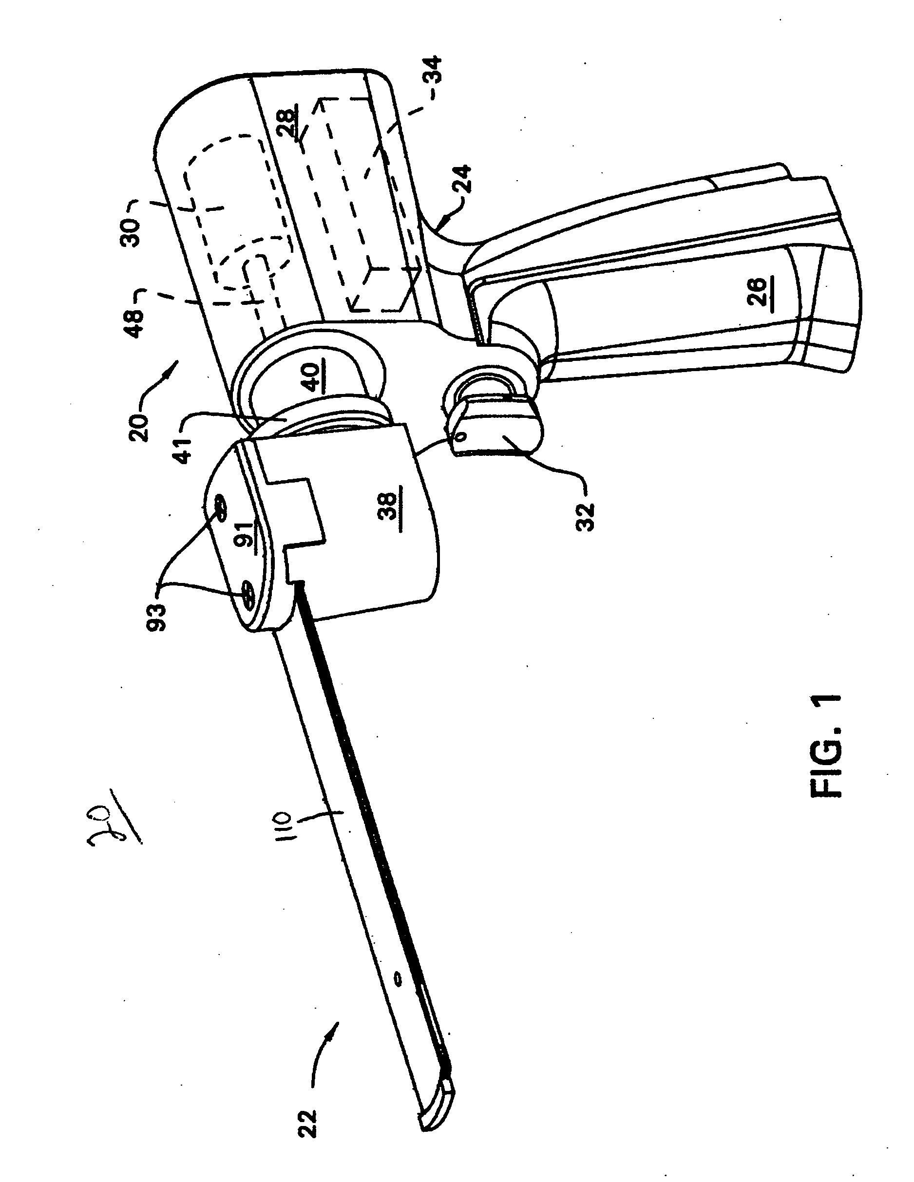
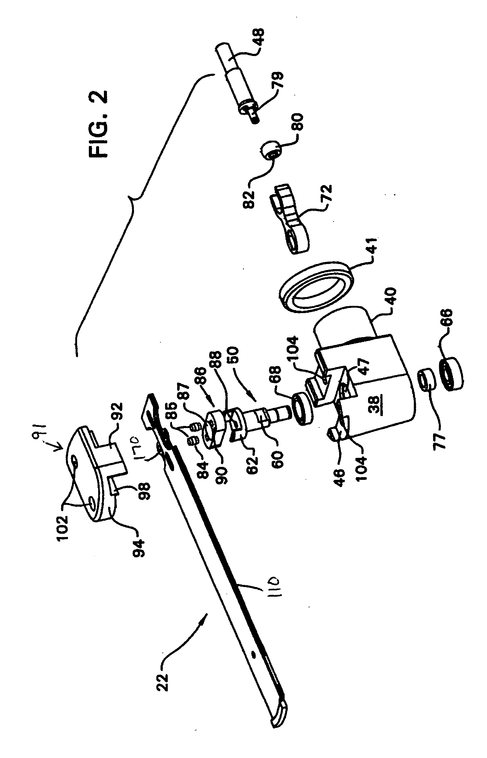
[0036]Referring to FIG. 1, in accordance with certain preferred embodiments of the present invention, an oscillating tip saw 20 includes a cutting blade assembly 22 and a housing 24 that is attached to the cutting blade assembly. As will be described in more deta...


PUM


Abstract

A system for cutting bone includes a cutting guide including a metal block having a guide surface provided thereon, and an oscillating tip saw having a cutting blade assembly extending from a distal end thereof. At least one element of the cutting blade assembly is magnetic for generating a magnetic attraction to the guide surface of the cutting guide so as to control the orientation of the cutting blade assembly during a bone cutting procedure. The cutting guide may also be magnetic.

Description

FIELD OF THE INVENTION[0001]The present invention generally relates to surgical tools and procedures and more specifically relates to surgical saws and cutting guides used for preparing bone sites for receiving implants.BACKGROUND OF THE INVENTION[0002]Prosthetic implants are frequently used to replace damaged natural joints in the body. During a surgical procedure, in order to prepare a stable implant site, it is usually necessary to remove additional bone beyond the damaged portion of the joint.[0003]During orthopedic implant procedures, saws are often used to selectively remove bone. During such procedures, it is very important to form precise cut lines in bone because the prosthetic implant parts are designed to fit snuggly in the prepared bone site. In order to insure that precise cut lines are formed, surgeons typically mount a cutting guide or cutting block to the bone adjacent to the location where the cut is to be made. One type of cutting guide has a precisely shaped set o...

Claims


Application Information

Patent Timeline
IPC IPC(8): A61F5/00A61B17/00A61B17/32
CPCA61B17/141A61B17/148A61B17/1707A61B17/15A61B17/14A61B17/142
Inventor MCCARTHY, THOMAS FRANCIS
Owner HOWMEDICA OSTEONICS CORP
Learn More