
Emissive displays having improved contrast

a technology of emissive display and contrast, which is applied in the direction of discharge tube luminescnet screen, discharge tube/lamp details, organic semiconductor device, etc., can solve the problems of difficult to design a display having suitable contrast ratio, difficult to view, and severe reduction of the luminance of the display, so as to increase the luminance and ambient contrast of the emissive display device

Active Publication Date: 2008-06-05
GLOBAL OLED TECH
View PDF5 Cites 30 Cited by
  • Summary
  • Abstract
  • Description
  • Claims
  • Application Information

AI Technical Summary

Benefits of technology

[0012]The present invention has the advantage that it increases both the luminance and ambient contrast of an emissive display device.

Problems solved by technology

Given the wide variety of viewing conditions proposed for emissive displays, it is difficult to design a display having suitable contrast ratio.
The reflective metals reflect ambient light towards a display viewer, thereby, making the display difficult to view.
However, this approach has the difficulty that most of the light emitted from the emissive layer toward the absorptive layer is lost, thereby, severely reducing the luminance of the display.
Such louver films are typically employed on the top surface of a display device, and while effective at reducing viewing angles, typically have not been suggested for use in displays to improve light output and ambient contrast.

Method used


Image

  • Emissive displays having improved contrast
  • Emissive displays having improved contrast
  • Emissive displays having improved contrast

Examples


Embodiment Construction

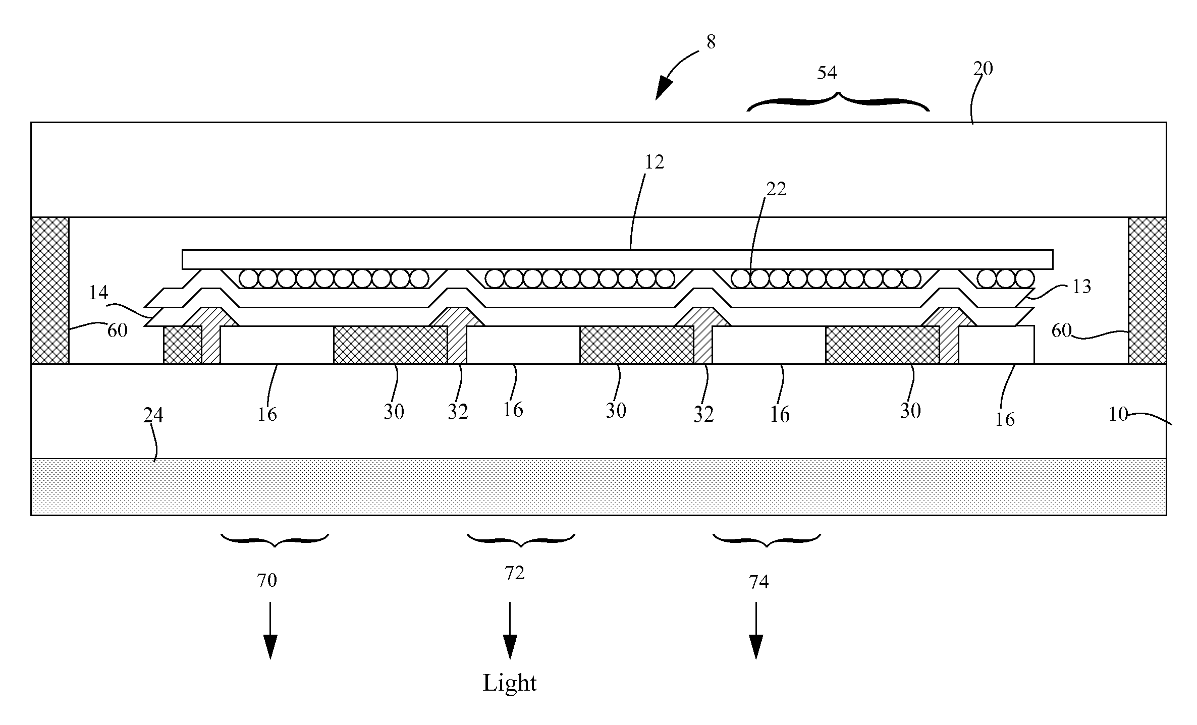
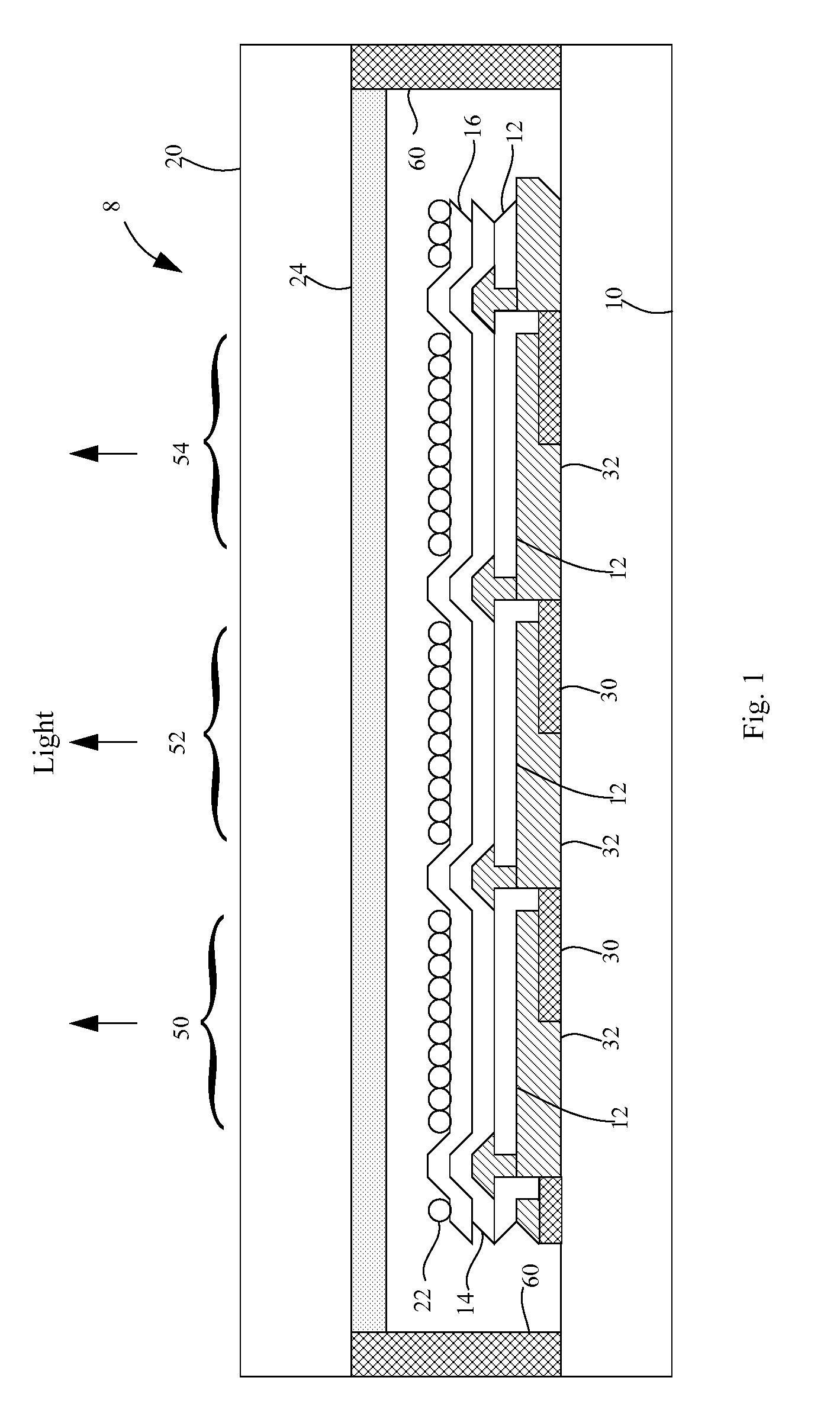
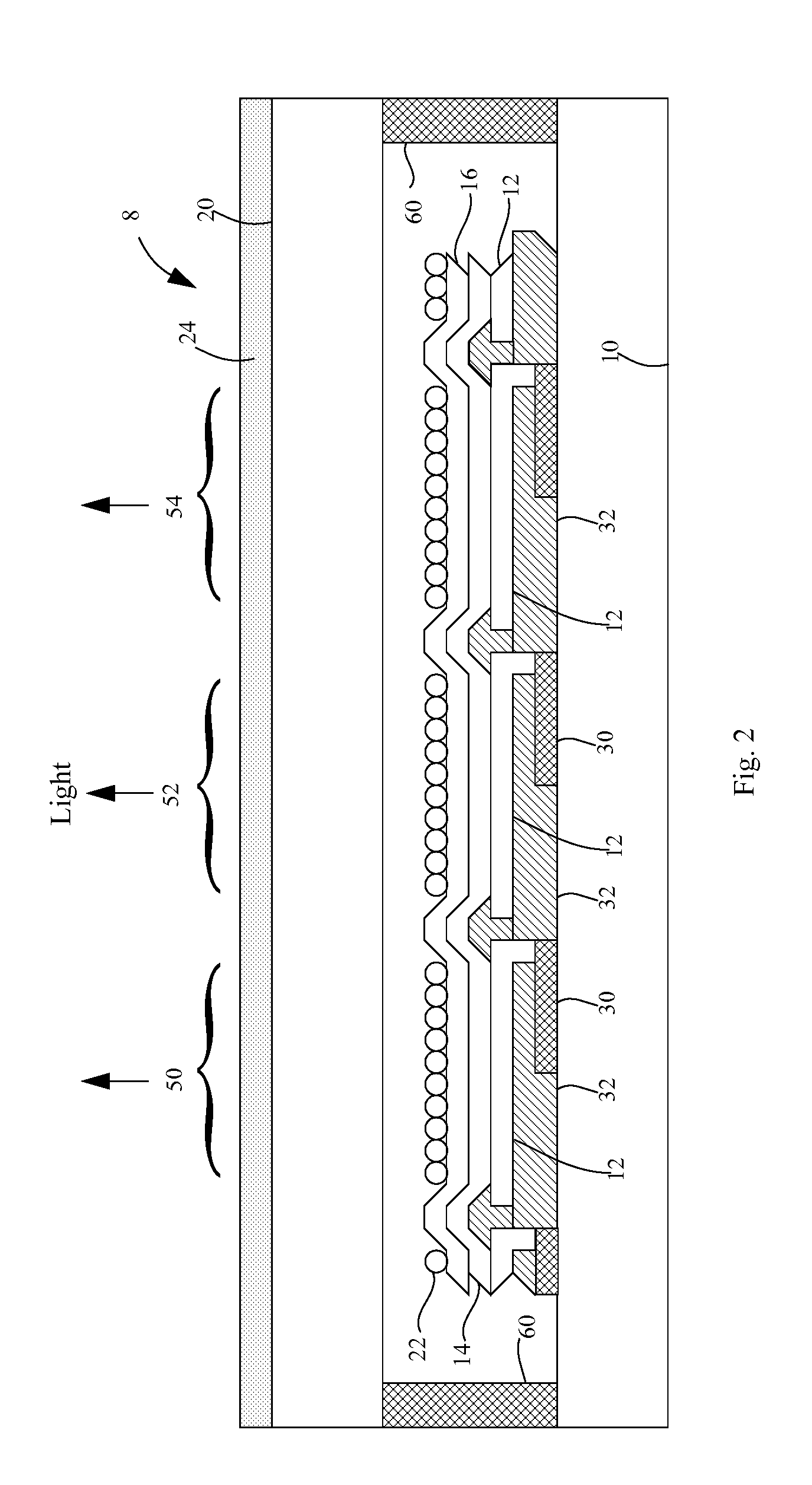
[0025]Referring to FIG. 1, an emissive display device 8 according to the present invention comprises a substrate 10; a reflective electrode 12 formed over the substrate 10; one or more light-emitting layers 14 formed over the substrate 10; a transparent electrode 16 formed over the one or more light-emitting layers 14, the reflective and transparent electrodes 12, 16 and one or more light-emitting layers 14 form a light-emitting element for emitting light in a direction of light emission, as defined by the pattern of the reflective electrode 12; a scattering layer 22 to scatter light trapped in the one or more light- emitting layers 14, a circular polarizer 24 located in the direction of light emission. Typically, in a display device, at least one of the reflective or transparent electrodes 12, 16 is patterned to define the light-emitting areas of the display. Thin-film electronic components 30 may be employed to provide current to the electrodes 12, 16 in response to signals. Such ...


PUM


Abstract

An emissive display device, including: a reflective electrode and a transparent electrode. One or more light-emitting layers are formed between the reflective and transparent electrodes. A scattering layer is positioned in the emissive display device to scatter light trapped in the one or more light-emitting layers; and a circular polarizer is located on the side of the scattering layer opposite the reflective electrode.

Description

FIELD OF THE INVENTION[0001]The present invention relates to emissive displays, and more particularly, to improving the contrast of displays having relatively high-index emissive layers.BACKGROUND OF THE INVENTION[0002]Flat-panel displays, such as organic light emitting diode (OLED) and inorganic emissive displays, of various sizes are proposed for use in many computing and communication applications. In particular, such displays are proposed for use in both indoor and outdoor applications under a wide variety of ambient lighting conditions. Indoor applications have relatively low ambient illumination and require lower levels of display luminance. In contrast, outdoor applications can have a high ambient luminance and may require higher levels of display luminance together with low display reflectance. Moreover, most emissive displays are proposed for use in conditions that can be high, or low, or even non-existent ambient illumination; for example, illumination from outdoor use dur...

Claims


Application Information

Patent Timeline
Patent Type & Authority Applications(United States)
IPC IPC(8): H01J1/70
CPCB82Y20/00B82Y30/00H01L27/322H01L2251/5369H01L51/5268H01L51/5281H01L51/5284H01L51/5012H10K59/38H10K50/11H10K2102/331H10K59/877H10K59/8792H10K50/854H10K50/86H10K50/865
Inventor COK, RONALD S.
Owner GLOBAL OLED TECH
Learn More