LED device having improved contrast

a technology of led devices and diodes, which is applied in the manufacture of electrode systems, electric discharge tubes/lamps, discharge tubes luminescnet screens, etc., can solve the problems of affecting the effectiveness of circular polarizers, affecting the light output of led devices, and affecting the effect of ambient contras

Active Publication Date: 2008-12-11
GLOBAL OLED TECH
View PDF23 Cites 25 Cited by
  • Summary
  • Abstract
  • Description
  • Claims
  • Application Information

AI Technical Summary

Benefits of technology

[0009]The present invention has the advantage that it increases the light output and ambient contrast of an LED device.

Problems solved by technology

As is known in the prior art, circular polarizers can greatly reduce the reflected ambient light, but such circular polarizers are expensive.
Significant portions of emitted light may also be trapped in LED devices.
Scattering layers may be employed to improve the light emission of LED devices, but may inhibit the effectiveness of circular polarizers, and do not selectively absorb ambient light.
However, this reduces the amount of area available for a black matrix, thereby increasing the amount of ambient light reflected from the LED back electrode and reducing the contrast of a top-emitting LED device.
However, such a design requires small, high-precision features.
Moreover, any imperfection in the reflective layer reduces the absorption of the ambient light and ambient contrast ratio of the device.

Method used


Image

  • LED device having improved contrast
  • LED device having improved contrast
  • LED device having improved contrast

Examples


Embodiment Construction

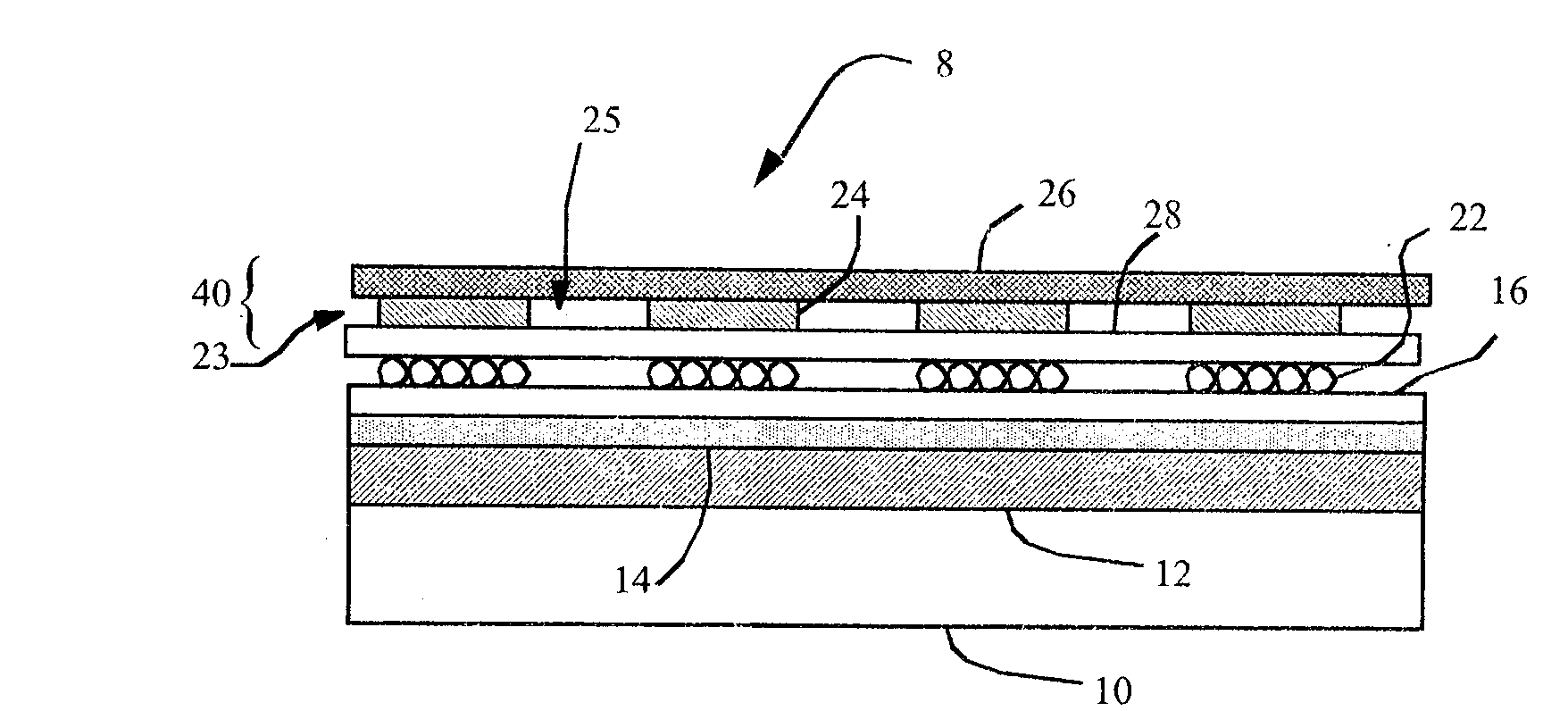
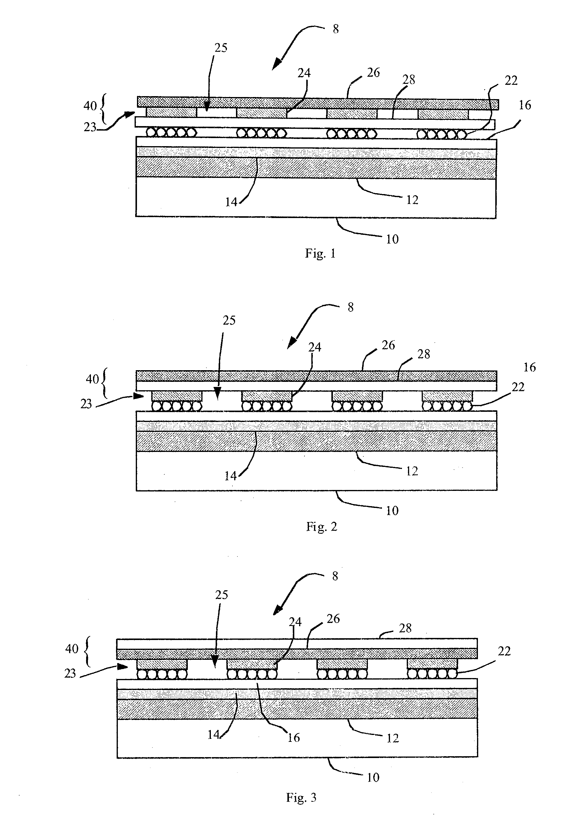
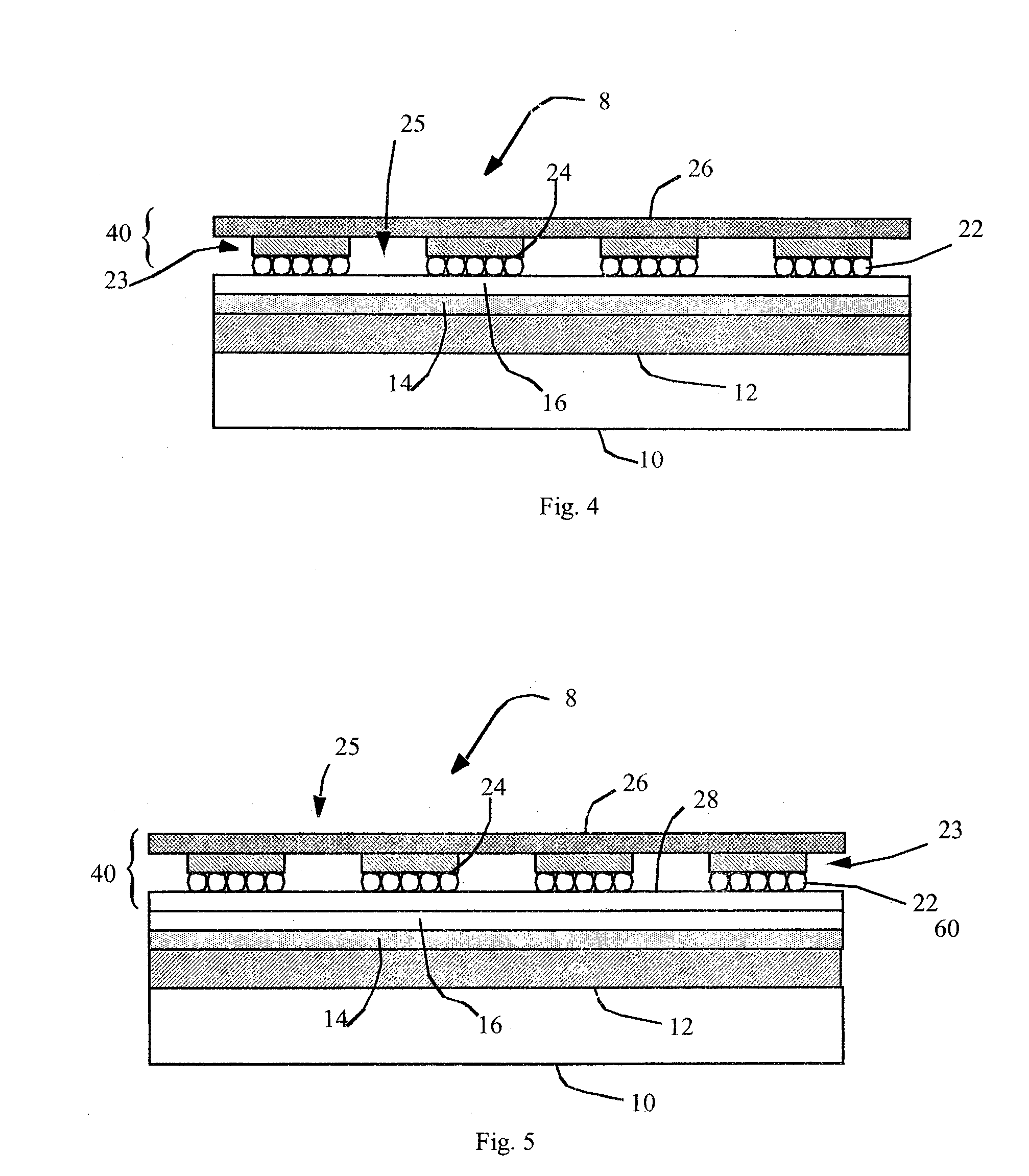
[0024]Referring to FIG. 1, according to one embodiment of the present invention, a light-emitting diode (LED) device 8 comprises a substrate 10 and a reflective electrode 12 and a transparent electrode 16 formed on the substrate 10. One or more light-emitting layers 14 are formed between the electrodes 12, 16. A contrast-enhancement element 40 is located on a side of the transparent electrode 16 opposite the light-emitting layer 14, the contrast-enhancement element 40 having a first reflected-light absorbing layer 26 and a second layer 23 including transparent areas 25 and reflective areas 24, and wherein the second layer 23 is between the first reflected-light absorbing layer 26 and the reflective electrode 12. A patterned light-scattering layer 22 is located between the reflective areas 24 of the second layer 23 and the reflective electrode 12. The reflective areas 24 screen the scattering areas of the patterned light-scattering layer 22 from ambient illumination; thereby, enablin...


PUM


Abstract

A light-emitting diode (LED) device includes a reflective electrode and a transparent electrode having one or more light-emitting layers formed there-between. A contrast-enhancement element is located on a side of the transparent electrode opposite the light-emitting layer. The contrast-enhancement element has a first reflected-light absorbing layer and a second layer including transparent areas and reflective areas. The second layer is between the first reflected-light absorbing layer and the reflective electrode. A patterned light-scattering layer is located between the reflective areas of the second layer and the reflective electrode.

Description

FIELD OF THE INVENTION[0001]The present invention relates to light-emitting diode (LED) devices, and more particularly, to LED device structures for improving light output and ambient contrast.BACKGROUND OF THE INVENTION[0002]Light-emitting diodes (LEDs) are a promising technology for flat-panel displays and area illumination lamps and backlights. However, LED devices typically have a highly reflective back electrode to enhance the output of emitted light through one side of the LED device. This highly reflective back electrode also reflects ambient light, thereby reducing the ambient contrast ratio of the LED device. As is known in the prior art, circular polarizers can greatly reduce the reflected ambient light, but such circular polarizers are expensive.[0003]Significant portions of emitted light may also be trapped in LED devices. Scattering layers may be employed to improve the light emission of LED devices, but may inhibit the effectiveness of circular polarizers, and do not s...

Claims


Application Information

Patent Timeline
Patent Type & Authority Applications(United States)
IPC IPC(8): H01J1/62H01J9/18
CPCH01L51/5268H01L51/5284H10K50/854H10K50/865
Inventor COK, RONALD S.
Owner GLOBAL OLED TECH
Why Eureka
Try Eureka