Keyed push-pull type fiber optic connection system

Inactive Publication Date: 2008-06-05
CORNING CABLE SYST LLC
View PDF31 Cites 35 Cited by
  • Summary
  • Abstract
  • Description
  • Claims
  • Application Information

AI Technical Summary

Benefits of technology

[0009]The present invention overcomes many of the disadvantages of the prior art by providing for a connection system that may be successfully implemented in push-pull type fiber optic connector plugs and receptacle sockets. The push-pull type connector plug and receptacle socket found in the present invention include protrusions, channels, and slots located on their respective inner and / or outer surfaces, which allow them to successfully interconnect, while restricting interconnectivity among devices not properly keyed.

Problems solved by technology

Thus, a standard non-keyed connector plug may not be inserted into a properly keyed receptacle socket by removing the outer housing of the connector plug.
The protrusions and channels / slots found on the connector's inner and outer housing do not prevent the connector's inner housing from sliding within the connector's outer housing.

Method used


Image

  • Keyed push-pull type fiber optic connection system
  • Keyed push-pull type fiber optic connection system
  • Keyed push-pull type fiber optic connection system

Examples


Embodiment Construction

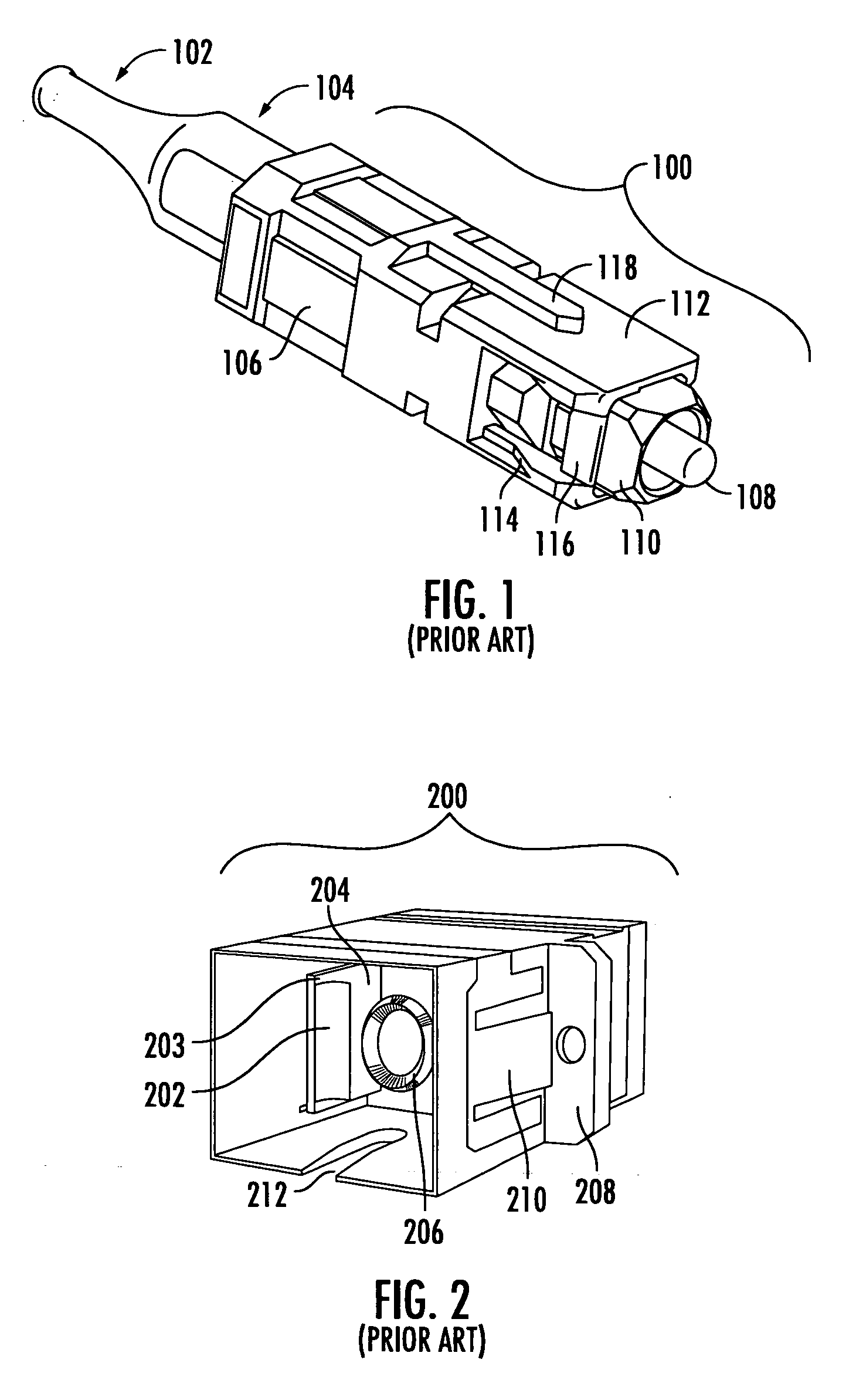
[0030]Commonly used types of push-pull connectors are “MU” and “SC” style fiber optic connector plugs. Referring to FIG. 1 and FIG. 2, embodiments of an SC style fiber optic connector plug 100 and a corresponding receptacle socket 200 found in the prior art are shown for comparison. SC and MU connectors are similar in function, thus keying options may apply to both the SC and MU connector types. The connector plug shown in FIG. 1 and the receptacle socket shown in FIG. 2 do not possess the keying features of the present invention, but are merely an example of an SC type connector plug and receptacle socket that may be found in the prior art. The connector plug 100 may be mounted to the end of a fiber optic line that is inserted through lead-in end 102. A strain relieving boot 104 provides protection from forces that may be applied to the joint (not shown) connecting the fiber optic line to the connector plug 100. The fiber optic line is comprised of both a light transmitting optical...


PUM


Abstract

A connection system for providing selective interconnection between a fiber optic connector plug and a receptacle socket. The connection system is configured for implementation in push-pull type connectors having a dual housing structure, including an inner housing and an outer housing. The connection system comprises a connector inner housing and connector outer housing having predefined keying geometries, including protrusions and channels / slots that may be formed onto the outer and inner surfaces of the respective connection devices. The connection system further comprises a receptacle socket, including protrusions and channels that may be formed onto the inner surface of the connection device. The protrusions and channels formed on the connector's inner and outer housing are configured to mate with corresponding keying features found on the receptacle socket, thus allowing properly keyed connection devices to interconnect.

Description

FIELD OF THE INVENTION[0001]The present invention relates to fiber optic connectors, and specifically, to a connection system for mating a fiber optic connector plug with a receptacle socket, each having corresponding keying features formed on their respective inner and / or outer surfaces, such that only properly keyed connection devices may interconnect with one another.DESCRIPTION OF THE RELATED ART[0002]A connector plug may be mounted on the terminal end of a fiber optic line in order to aid in further connecting the line. Fiber optic lines may be connected to other fiber optic lines in order to increase the overall length of a transmission line. A fiber optic line may also be connected to a terminal device designed to receive signals transmitted through said line. However, disruptions in signal transmission may occur any time a fiber optic line is terminated.[0003]Various interconnectivity devices are revealed in the prior art which seek to minimize the potential losses that may ...

Claims


Application Information

Patent Timeline
IPC IPC(8): G02B6/36
CPCG02B6/3831G02B6/3825G02B6/3893
Inventor PARKMAN, L. EDWARDTRAVIS, PETER
Owner CORNING CABLE SYST LLC
Why Eureka
Try Eureka