Filter element and method for manufacturing the same

a filter element and filter element technology, applied in the field of filter elements, can solve the problems of reducing the manufacturability of elements and difficulty in adjusting the resonant characteristics, and achieve the effect of enhancing the manufacturability and enhancing the manufacturability of filter elements

Active Publication Date: 2008-06-19
MURATA MFG CO LTD
View PDF6 Cites 4 Cited by
  • Summary
  • Abstract
  • Description
  • Claims
  • Application Information

AI Technical Summary

Benefits of technology

[0012]Specifically, by setting the line width of a resonant-line side portion slightly larger than the line width of a resonant-line main-surface portion, the resonant frequency of a corresponding strip-line resonator can be increased. By setting the line width of the resonant-line side portion smaller than the line width of the resonant-line main-surface portion, the resonant frequency of the strip-line resonator can be reduced. By setting a small spacing between resonant-line side portions of adjacent strip-line resonators, the degree of coupling between the strip-line resonators can be strengthened. By setting a large spacing between resonant-line side portions of adjacent strip-line resonators, the degree of coupling between the strip-line resonators can be weakened.
[0037]Preferred embodiments of the present invention can adjust the resonant characteristics of a strip-line resonator by adjustment of a resonant line on a side of a dielectric substrate and can provide a filter element that realizes desired resonant characteristics. The method for manufacturing a filter element according to a preferred embodiment of the present invention enables adjustment of the characteristics of a strip-line resonator even after a circuit pattern or an insulating layer is formed on a main surface of a dielectric substrate and can significantly enhance manufacturability.

Problems solved by technology

As a result, it is difficult to adjust the resonant characteristics after the circuit pattern is printed on the main surface of the dielectric substrate (dielectric base substrate).
If the resonant characteristics of a strip-line resonator vary from a design value in a step of printing a circuit pattern, a subsequent step of dividing into element bases, or another step, a defective element having resonant characteristics different from the design value would be produced, thus causing a problem of decreasing manufacturability of elements.

Method used


Image

  • Filter element and method for manufacturing the same
  • Filter element and method for manufacturing the same
  • Filter element and method for manufacturing the same

Examples


Embodiment Construction

[0044]A filter element according to a first preferred embodiment of the present invention will be described with reference to the drawings. The Cartesian coordinate system (X-Y-Z axes) shown in the drawings is used in description here.

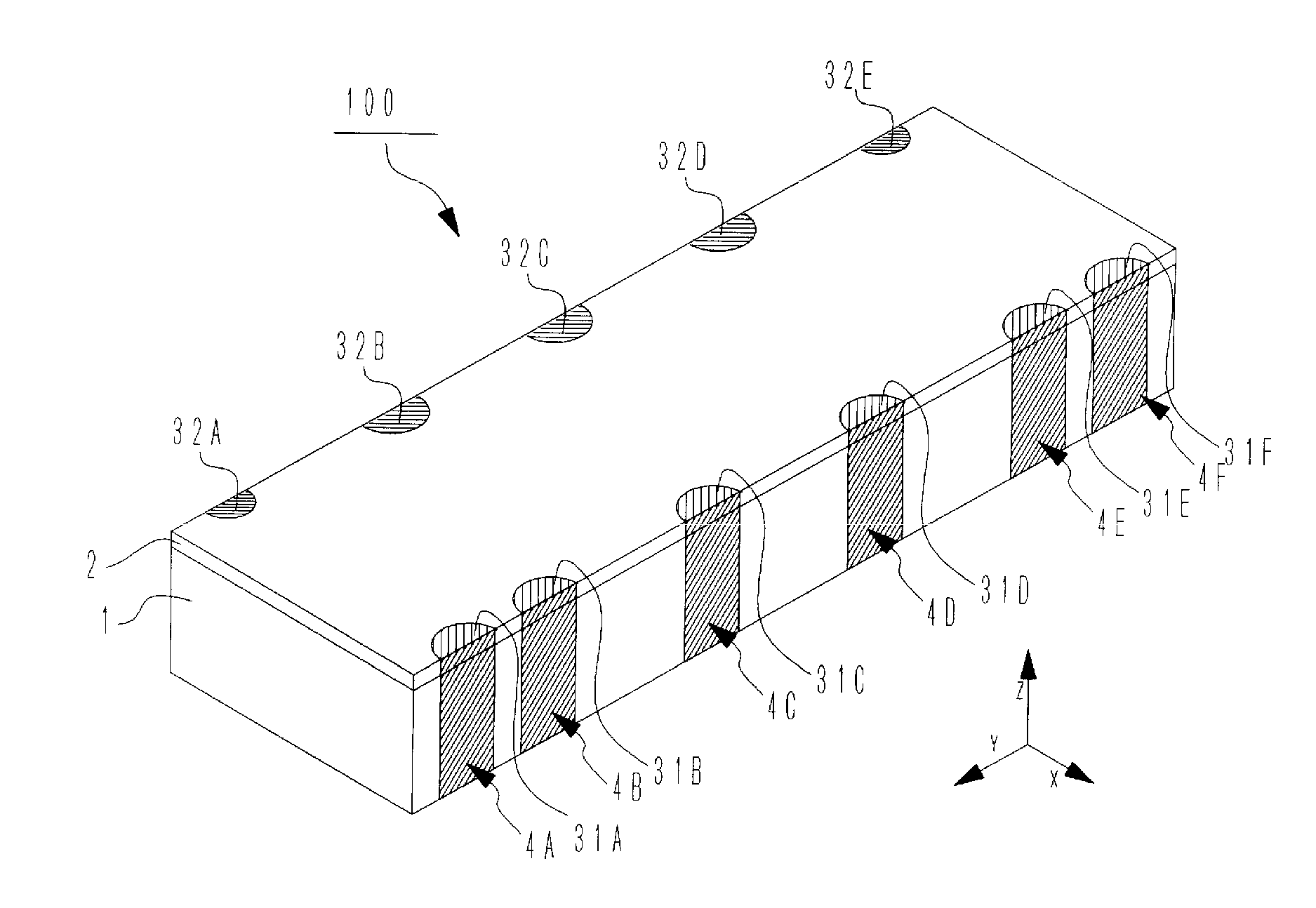
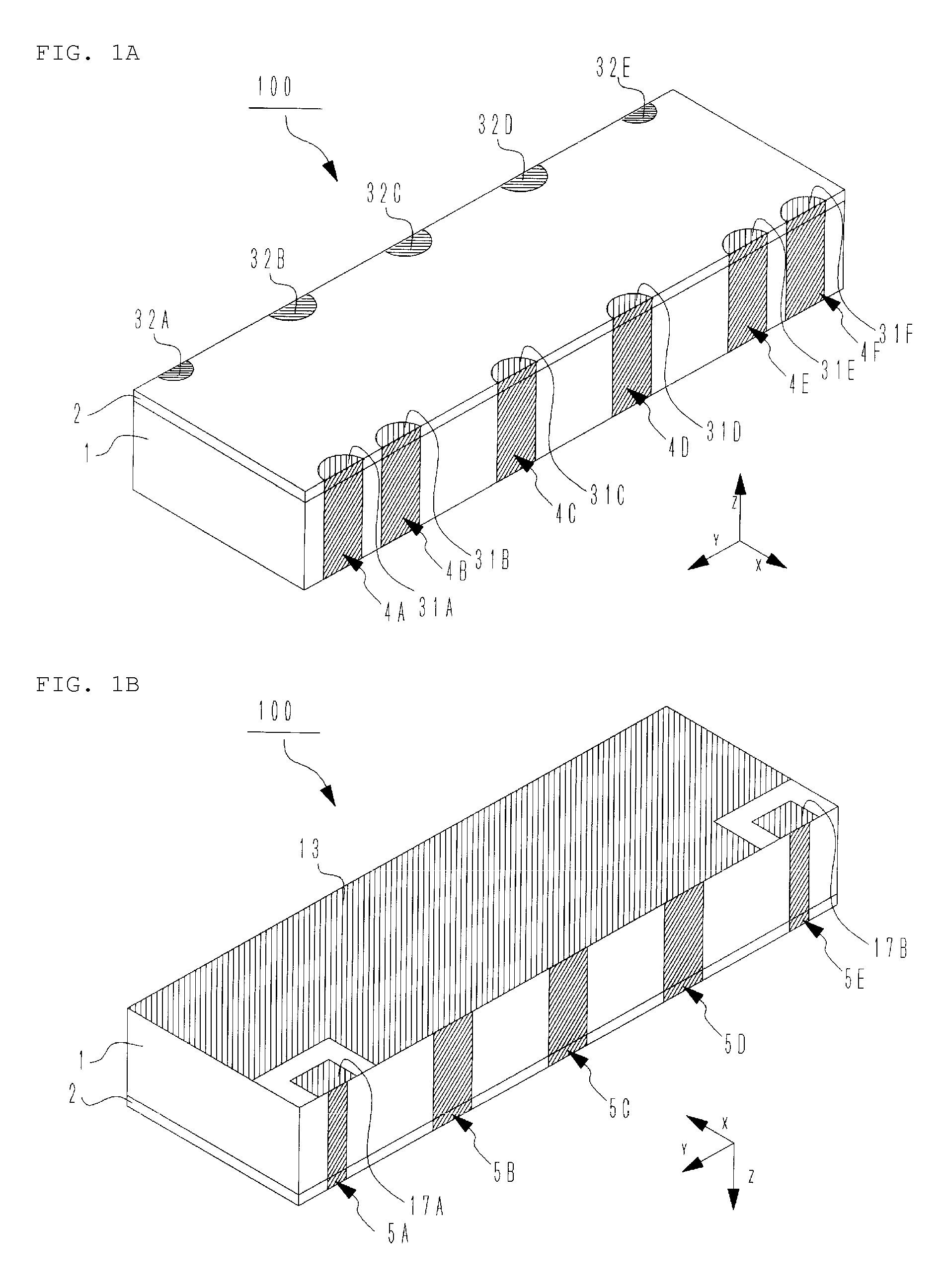
[0045]First, a general configuration of a filter element 100 according to the present preferred embodiment will be described. FIGS. 1A and 1B are external views of the filter element 100 according to the present preferred embodiment. FIG. 1A is a perspective view of the filter element 100 with the front (+Y plane) being oriented to the left near side of the drawing. FIG. 1B is a perspective view that illustrates a state in which the filter element 100 shown in FIG. 1A is rotated 180° about the Y-axis.

[0046]The filter element 100 used for description in the present preferred embodiment is a filter element preferably having a substantially rectangular parallelepiped configuration. In the filter element 100, a front main surface of a dielectric substrate ...


PUM


Abstract

A filter element includes a flat dielectric substrate, a ground electrode on a back main surface of the dielectric substrate, resonant lines each having a shorting end in the vicinity of a border between a side of the dielectric substrate and the ground electrode and extending from the side to a front main surface of the dielectric substrate. The resonant lines and the ground electrode constitute strip-line resonators. In any of the strip-line resonators, the line width of the resonant-line side portion is different from the line width of the resonant-line main-surface portion.

Description

BACKGROUND OF THE INVENTION[0001]1. Field of the Invention[0002]The present invention relates to a filter element in which a strip-line resonator is disposed on a dielectric substrate. The present invention also relates to a method for manufacturing a filter element.[0003]2. Description of the Related Art[0004]There are previously known filter elements that have wide-band frequency characteristics utilizing a coupling of a plurality of strip-line resonators.[0005]Japanese Unexamined Patent Application Publication No. 10-65401 discloses a filter element in which a plurality of strip-line resonators disposed on a single dielectric substrate serve as filters. The filter element includes a ground electrode on a back main surface and a side surface of the flat dielectric substrate and also includes resonant lines each having a shorting end in the vicinity of a border between the side surface and a front main surface. The shorting ends of adjacent strip-line resonators are positioned in t...

Claims


Application Information

Patent Timeline
Patent Type & Authority Applications(United States)
IPC IPC(8): H01P1/205
CPCH01P11/007H01P1/20336
Inventor TSUJIGUCHI, TATSUYAKITAICHI, YUKIHIRO
Owner MURATA MFG CO LTD
Why Eureka
Try Eureka