Apparatus And Method For Simulating Vision Correction

a technology of simulating vision and glasses, applied in the field of systems and methods for simulating vision correction, can solve the problems of inability to correct current-manufactured glasses or contact lenses, and higher-order aberrations are refractive errors in the living ey

Inactive Publication Date: 2008-06-19
UNIVERSITY OF ROCHESTER
View PDF15 Cites 57 Cited by
  • Summary
  • Abstract
  • Description
  • Claims
  • Application Information

AI Technical Summary

Benefits of technology

[0023]It is still another object of the present invention to diagnose and simulate correction of visual acuity problems associated with astigmatism and myopia together with higher order aberrations.
[0024]Briefly described, these and other objects and features of the present invention are accomplished, as embodied and fully described herein, by a higher order aberration diagnostic device that is adapted to identify aberrations and simulate the correction of those aberrations. The device includes a trial lens set having a first trial lens, wherein the first trial lens is adapted to being positioned proximate a living eye for identifying a higher order aberration associated with the eye. The trial lens set may further have a second trial lens, wherein the second trial lens is adapted to being positioned proximate the eye for identifying a second higher order aberration or, in combination with the first trial lens, for identifying the higher order aberration. The trial lens may be a spectacle lens, contact lens, or other lens type.
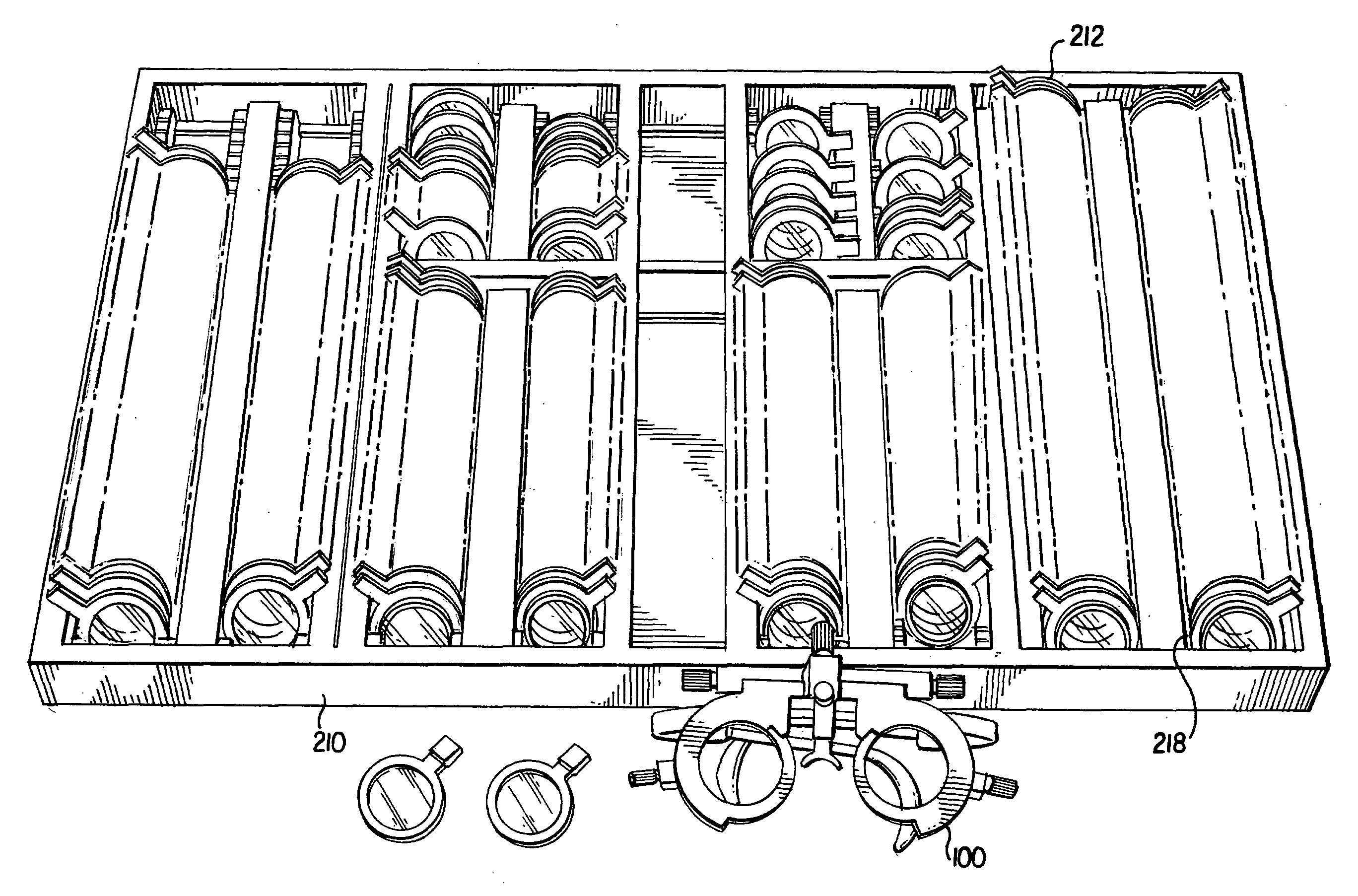
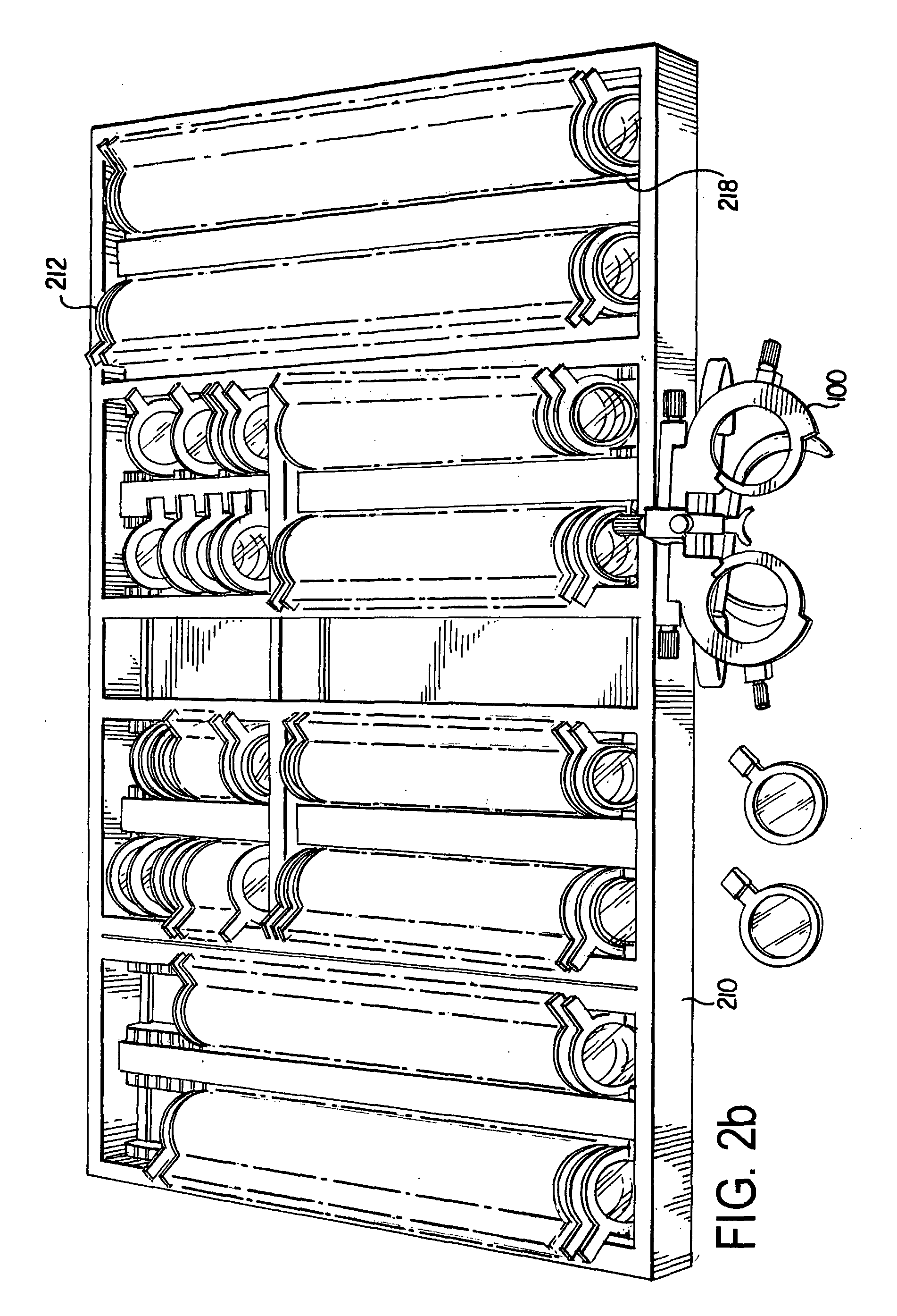
[0025]The objects and features of the present invention are also accomplished, as embodied and fully described herein, by a trial lens set having a plurality of trial lenses, wherein at least one of the plurality of trial lenses is adapted to being positioned proximate the eye for identifying and simulating the correction of a higher order aberration, which could be a second, third, fourth, or fifth mode aberration. The invention may also include a carrying case adapted to holding the plurality of trial lenses. The plurality of trial lenses may be spectacle, contact, or some other type of lens.
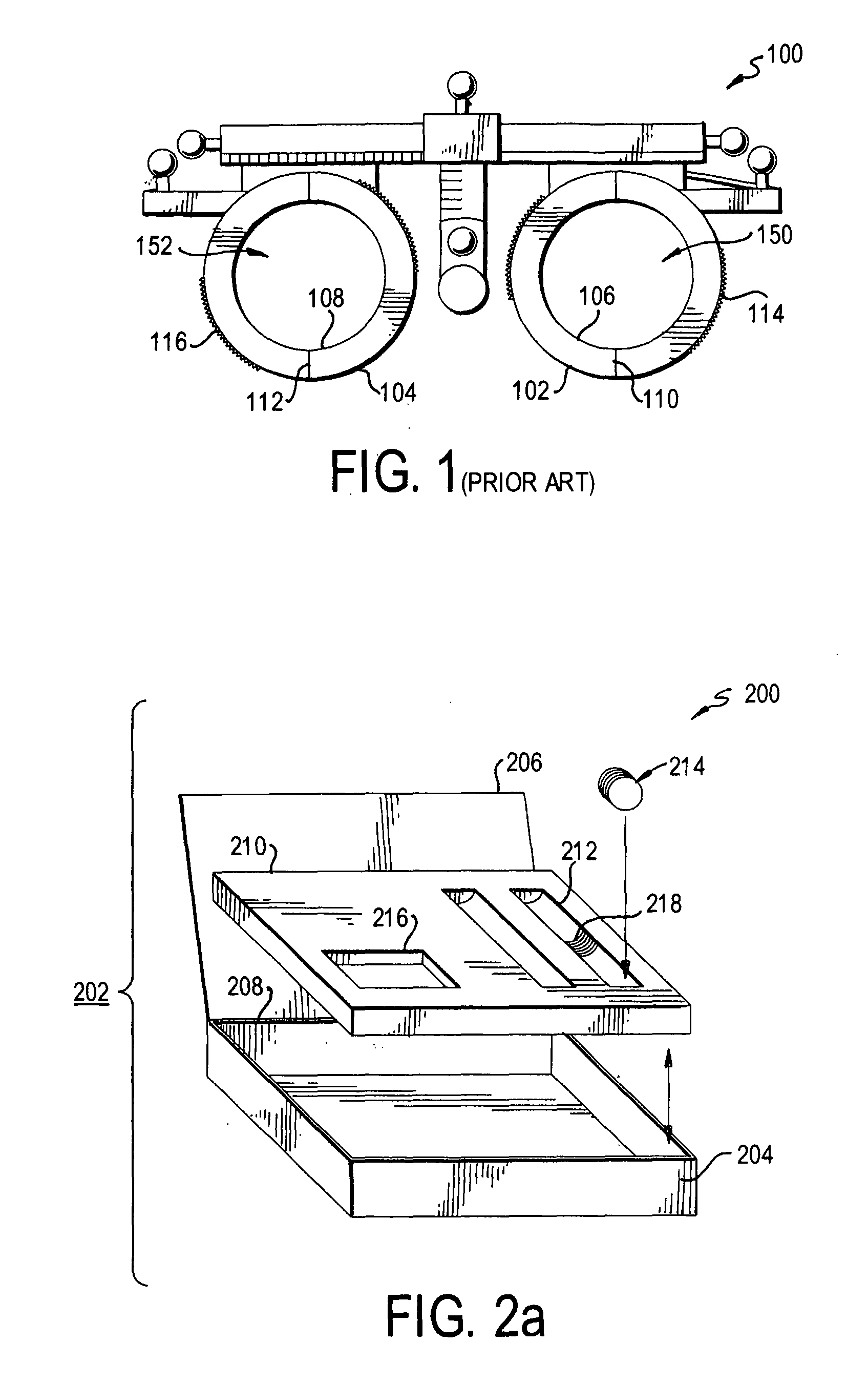
[0026]The objects and features of the present invention are also accomplished, as embodied and fully described herein, by an ophthalmic diagnostic device having a trial spectacle frame adapted to be worn proximate a living eye of a patient, a plurality of trial lenses adapted to be attached to the trial frame, and a carrying case for holding the trial frame and the plurality of trial lenses. In that embodiment, at least one of the plurality of trial lenses is used to identify and simulate the correction of a higher order aberration associated with the living eye of the patient, including correcting a third, fourth and fifth higher order aberration or a combination of higher order aberrations as selected by the practitioner.
[0027]The objects and features of the present invention are accomplished, as embodied and fully described herein, by an ophthalmic device for diagnosing visual acuity problems, the device having a phoropter frame adapted to being placed proximate a living eye of a patient, the frame having at least one through hole; at least one trial lens frame positioned within the phoropter frame; and a plurality of trial lenses adapted to being attached to the at least one trial lens frame. The at least one trial lens frame is moveable relative to the phoropter frame such that at least one of the plurality of trial lenses is positioned proximate the at least one through hole, and at least one of the plurality of trial lenses is adapted to identifying and simulating the correction of a higher order aberration associated with the living eye of the patient. In that embodiment, at least one of the plurality of trial lenses is adapted to identifying astigmatism and at least one of the plurality of trial lenses is adapted to identifying myopia. The at least one trial lens frame may be a wheel that is rotatably moveable relative to the phoropter frame and is adapted to identify and simulate the correction of different higher order aberrations as described by Zernike, Fourier, or any other mathematical method of describing wavefront error.
[0028]Finally, the object and features of the present invention are accomplished, as embodied and fully described herein, by a method for using trial lenses to identify higher order aberrations in the living eye of a patient and simulating the correction of those aberrations prior to prescribing a lens for use by the patient.

Problems solved by technology

Higher order aberrations are refractive errors in the living eye, other than nearsightedness, farsightedness, and astigmatism, which cannot be corrected with currently-manufactured glasses or contact lenses.

Method used


Image

  • Apparatus And Method For Simulating Vision Correction
  • Apparatus And Method For Simulating Vision Correction
  • Apparatus And Method For Simulating Vision Correction

Examples


Embodiment Construction

[0041]Several preferred embodiments of the invention are described for illustrative purposes, it being understood that the invention may be embodied in other forms not specifically shown in the drawings.

[0042]Tuning first to FIG. 1, shown therein is a perspective view of a prior art trial lens spectacle-type frame 100. A trial lens frame, also known as a simple phoropter, is used to hold trial lenses proximate a living eye so a doctor can simulate a patient's corrected vision in a clinical setting, such as at a doctors office. Often, patients suffering from myopia (nearsightedness, short-sightedness), hypermetropia (farsightedness, long-sightedness), astigmatism, or higher order aberrations may not fully appreciate his or her corrected vision by simply sitting behind a suspended phoropter and looking at the letters and numbers on an spot-lit acuity chart. By wearing the trial frame 100, the patient can walk around the office or outside, read a book, look at distant and near objects,...


PUM


Abstract

An ophthalmic diagnostic device is disclosed having a trial spectacle frame (100), phoropter (900), or other device adapted to be placed proximate a living eye of a patient, and having a set of trial lenses (300) adapted to be attached to the device. At least one of the trial lenses is adapted to correcting a higher order aberration associated with the living eye of the patient, including correcting a third, fourth and fifth higher order aberration or a combination of higher order aberrations as selected by the patient's healthcare practitioner.

Description

CROSS REFERENCE TO RELATED APPLICATIONS[0001]This application is related to U.S. Provisional Patent Application Ser. No. 60 / 629,338, entitled “VISION DIAGNOSTIC DEVICE,” filed on Nov. 22, 2004, which is expressly incorporated by reference herein.BACKGROUND OF THE INVENTION[0002]1. Field of Invention[0003]The present invention relates to systems and methods for simulating vision correction. In particular, the present invention relates to a trial lens set for identifying or confirming aberrations of a living eye of a patient and simulating correction of higher order aberrations in the patient's eye.[0004]2. Description of the Related Art[0005]Higher order aberrations are refractive errors in the living eye, other than nearsightedness, farsightedness, and astigmatism, which cannot be corrected with currently-manufactured glasses or contact lenses. University of Rochester researchers were pioneers in the discovery and classification of higher order aberrations, which has led to many new...

Claims


Application Information

Patent Timeline
Patent Type & Authority Applications(United States)
IPC IPC(8): A61B3/04
CPCA61B3/04
Inventor MACRAE, SCOTT M.
Owner UNIVERSITY OF ROCHESTER
Why Eureka
Try Eureka