Photographing optical system

a technology of optical system and photograph, applied in the field of compact photographing optical system, can solve the problems of increasing the size of the pixel of the sensor, the inability to the conventional lens system with three lens elements can no longer meet the photographing optical system of even higher level, so as to reduce the total track length and reduce the photosensitivity of the photographing optical system. , the effect of high image resolution

Active Publication Date: 2013-06-04
LARGAN PRECISION
View PDF3 Cites 7 Cited by
  • Summary
  • Abstract
  • Description
  • Claims
  • Application Information

AI Technical Summary

Benefits of technology

[0012]By such arrangement, the total track length and photosensitivity of the photographing optical system can be effectively reduced, and high image resolution can be obtained.
[0013]In the aforementioned photographing optical system, the first lens element has positive refractive power, which thereby can provide partial refractive power for the system and is favorable for reducing the total track length thereof. The second lens element has negative refractive power, and thereby the aberration and the chromatic aberration can be effectively corrected. The third lens element has positive refractive power, which thereby can cooperate with the first lens element to reduce the sensitivity of the system. The fourth lens element has negative refractive power, which thereby can provide partial negative refractive power for the system so that the high order aberration of the system can be effectively corrected.
[0014]In the aforementioned photographing optical system, when the first lens element has a convex object-side surface and a concave image-side surface, the astigmatism of the system can be corrected favorably so that the image resolution of the system can be favorably improved. When the second lens element has a concave object-side surface and a concave image-side surface, along with the negative refractive power thereof, the chromatic aberration can be favorably corrected. When the third lens element has a concave object-side surface and a convex image-side surface, the astigmatism and high order aberration of the system can be favorably corrected. When the fourth lens element has a concave image-side surface, the principal point of the optical system can be positioned away from the image plane and thereby reducing the total optical track length of the system for keeping the lens compact.

Problems solved by technology

However, as the improved process technology and the trend of electronic products with compact appearance, the pixel size of sensors is getting smaller, and the demand for lens element featuring better image quality increases.
Therefore, a conventional lens system with three lens elements can no longer satisfy photographing optical systems of even higher level.
First, the degree of freedom in arranging the lens system is curtailed due to the employment of excessive number of spherical glass lenses; thus, the total track length of the system cannot be reduced easily.
Second, the process of adhering glass lenses together is complicated, posing difficulties in manufacturing.
Moreover, as the size of imaging lens systems is becoming smaller and the specification thereof is becoming higher, assembling lens elements compactly within a limited space tend to cause unwanted light rays to reflect too many times within a lens barrel, which will affect image quality.

Method used


Image

  • Photographing optical system
  • Photographing optical system
  • Photographing optical system

Examples


first embodiment

[0071]Please refer to FIG. 23, which shows the distance and relative positions represented by SAG41max, SAG42max, Yp41 and Yp42 of the present photographing optical system. FIG. 23 is an enlarged drawing of a fourth lens element of the present invention (which will be described in more details below). A maximal distance between an on-axis site 2302 on which the object-side surface 141 of the fourth lens element 140 projects and an on-axis vertex 2301 of the object-side surface 141 is SAG41max, a maximal distance between an on-axis site 2304 on which the image-side surface 142 of the fourth lens element 140 projects and an on-axis vertex 2303 of the image-side surface 142 is SAG42max. A height between an optical axis and a site 2305 on the object-side surface 141 of the fourth lens element 140 which has a maximal distance between a projective image of the object-side surface 141 on the optical axis to the on-axis vertex 2301 thereof is Yp41, a height between an optical axis and a sit...

embodiment 1

[0073

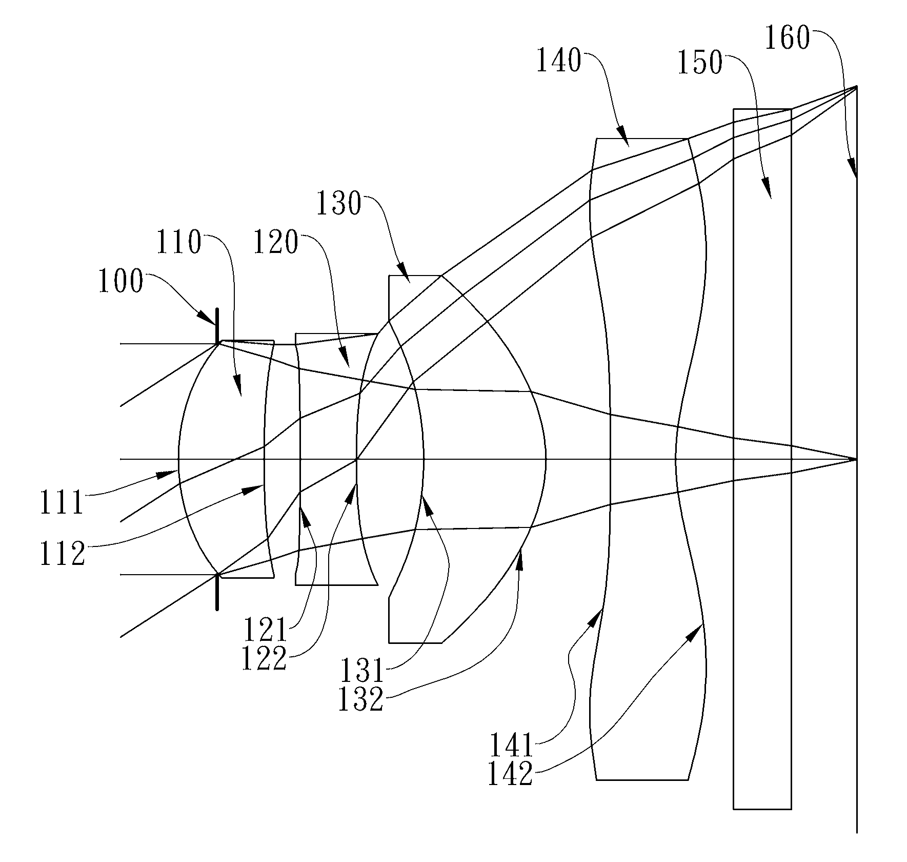
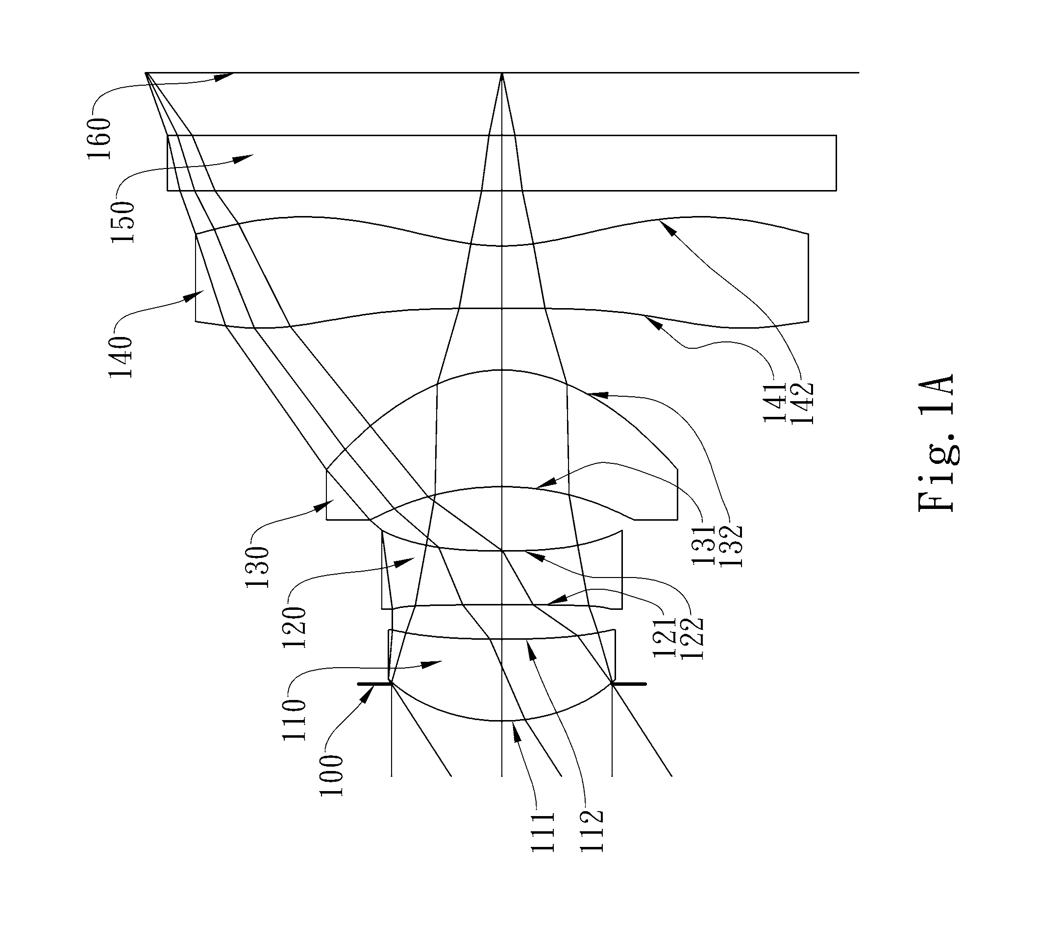
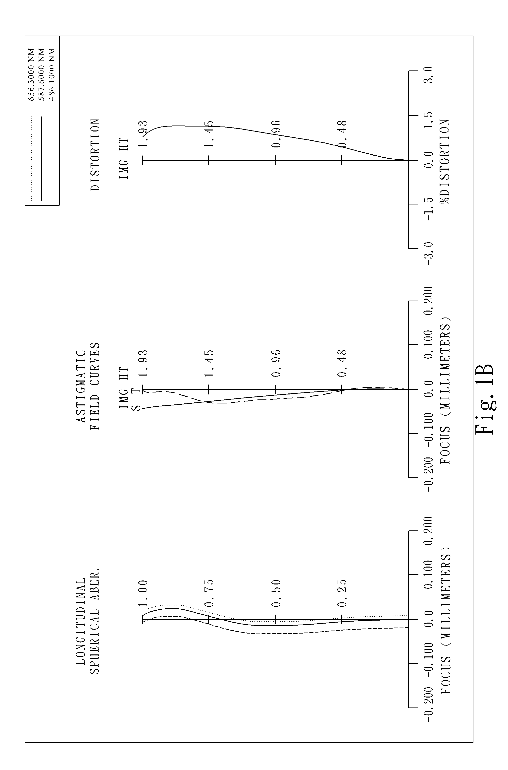
[0074]FIG. 1A shows a photographing optical system in accordance with the first embodiment of the present invention, and FIG. 1B shows the aberration curves of the first embodiment of the present invention. The photographing optical system of the first embodiment of the present invention mainly comprises four lens elements, in order from an object side to an image side:

[0075]a plastic first lens element 110 with positive refractive power having a convex object-side surface 111 and a concave image-side surface 112, the object-side and image-side surfaces 111 and 112 thereof being aspheric;

[0076]a plastic second lens element 120 with negative refractive power having a concave object-side surface 121 and a concave image-side surface 122, the object-side and image-side surfaces 121 and 122 thereof being aspheric;

[0077]a plastic third lens element 130 with positive refractive power having a concave object-side surface 131 and a convex image-side surface 132, the object-side and imag...

embodiment 2

[0105

[0106]FIG. 2A shows a photographing optical system in accordance with the second embodiment of the present invention, and FIG. 2B shows the aberration curves of the second embodiment of the present invention. The photographing optical system of the second embodiment of the present invention mainly comprises four lens elements, in order from an object side to an image side:

[0107]a plastic first lens element 210 with positive refractive power having a convex object-side surface 211 and a concave image-side surface 212, the object-side and image-side surfaces 211 and 212 thereof being aspheric;

[0108]a plastic second lens element 220 with negative refractive power having a concave object-side surface 221 and a concave image-side surface 222, the object-side and image-side surfaces 221 and 222 thereof being aspheric;

[0109]a plastic third lens element 230 with positive refractive power having a concave object-side surface 231 and a convex image-side surface 232, the object-side and i...


PUM


Abstract

This invention provides a photographing optical system, in order from an object side to an image side comprising: a first lens element with positive refractive power having a convex object-side surface and concave image-side surface; a second lens element with negative refractive power; a third lens element with positive refractive power having a concave object-side surface and a convex image-side surface; and a fourth lens element with negative refractive power having a concave image-side surface and both the object-side and image-side surfaces thereof being aspheric; wherein the photographing optical system has four lens elements with refractive power. By such arrangement, the total track length and photosensitivity of the photographing optical system can be effectively reduced, and high image resolution can be obtained.

Description

CROSS-REFERENCE TO RELATED APPLICATIONS[0001]This non-provisional application claims priority under 35 U.S.C. §119(a) on Patent Application No(s). 099141868 filed in Taiwan, R.O.C. on Dec. 2, 2010, the entire contents of which are hereby incorporated by reference.BACKGROUND OF THE INVENTION[0002]1. Field of the Invention[0003]The present invention relates to a photographing optical system, and more particularly, to a compact photographing optical system used in electronic products.[0004]2. Description of the Prior Art[0005]The demand for compact imaging lens assembly has grown in recent years as the popularity of portable electronic products with the photographing function has increased. The sensor of a general photographing camera is none other than CCD (Charge Coupled Device) or CMOS (Complementary Metal Oxide Semiconductor Sensor). Furthermore, as advanced semiconductor manufacturing technology has allowed the pixel size of sensors to be reduced, and the current electronic produc...

Claims


Application Information

Patent Timeline
Patent Type & Authority Patents(United States)
IPC IPC(8): G02B9/34
CPCG02B13/004G02B9/34
Inventor TANG, HSIANG CHIHUANG, HSIN HSUAN
Owner LARGAN PRECISION
Why Eureka
Try Eureka