Bath tub cushion

a technology for bathing tubs and cushions, applied in baths, douches, domestic applications, etc., can solve the problems of not providing any comfort to the person's hips, difficult to keep clean and maintain sanitary bath air cushions, and chairs are very expensive to produce, so as to prevent the movement of the back portion during use, prevent the movement of the bottom portion, and enhance the comfort of bathing

Inactive Publication Date: 2008-06-26
CLINE MARYANN +1
View PDF6 Cites 9 Cited by
  • Summary
  • Abstract
  • Description
  • Claims
  • Application Information

AI Technical Summary

Benefits of technology

[0007]According to the present invention, there is provided a bath tub cushion for lining at least one substantially vertically disposed predetermined end surface and a bottom surface of a bath tub to enhance comfort during bathing. The bath tub cushion will include a back portion, having each of a first predetermined width, a first predetermined length, a first predetermined shape and a predetermined number of fluid impermeable chambers formed therein. There is a first means disposed in fluid communication with an interior portion of such predetermined number of fluid impermeable chambers formed in the back portion for both inflating and deflating them as necessary or desirable. A second means is disposed on at least a portion of a back surface of such back portion and is placed into engagement with such substantially vertically disposed predetermined end of such bath tub for preventing movement of the back portion during use. The cushion has a bottom portion which extends toward an opposed end of such tub. The bottom portion is connected to a bottom edge of a front portion of the back portion for supporting a person's hips during bathing. Finally, there is a third means disposed on the bottom surface of the bottom portion which engages with the substantially horizontally disposed surface of such bath tub for preventing movement of the bottom portion during use.
[0008]It is, therefore, one of the primary objects of the present invention to provide a bath tub cushion which will substantially minimize slipping on the bottom surface of the tub during ingress and egress.
[0009]Another object of the present invention is to provide a bath tub cushion which is easier to keep clean and sanitary when compared to prior art devices.
[0010]Still another object of the present invention is to provide a bath tub cushion which is easy to remove from the tub to clean such tub after use.
[0011]Yet another object of the present invention is to provide a bath tub cushion which is relatively light weight as compared to other devices presently available.
[0012]An additional object of the present invention is to provide a bath tub cushion which is relatively inexpensive to manufacture when compared to presently available designs.

Problems solved by technology

However, this does not provide any comfort to the person's hips while sitting in the tub.
As is evident from this description this bath air cushion is difficult to keep clean and maintain sanitary.
This makes the chair very expensive to produce due to the numerous sizes and shapes of patients and has therefore not been widely accepted in the marketplace.

Method used


Image

  • Bath tub cushion
  • Bath tub cushion
  • Bath tub cushion

Examples


Embodiment Construction

, particularly, when such description is taken in conjunction with the attached drawing figures and with the appended claims.

BRIEF DESCRIPTION OF THE DRAWINGS

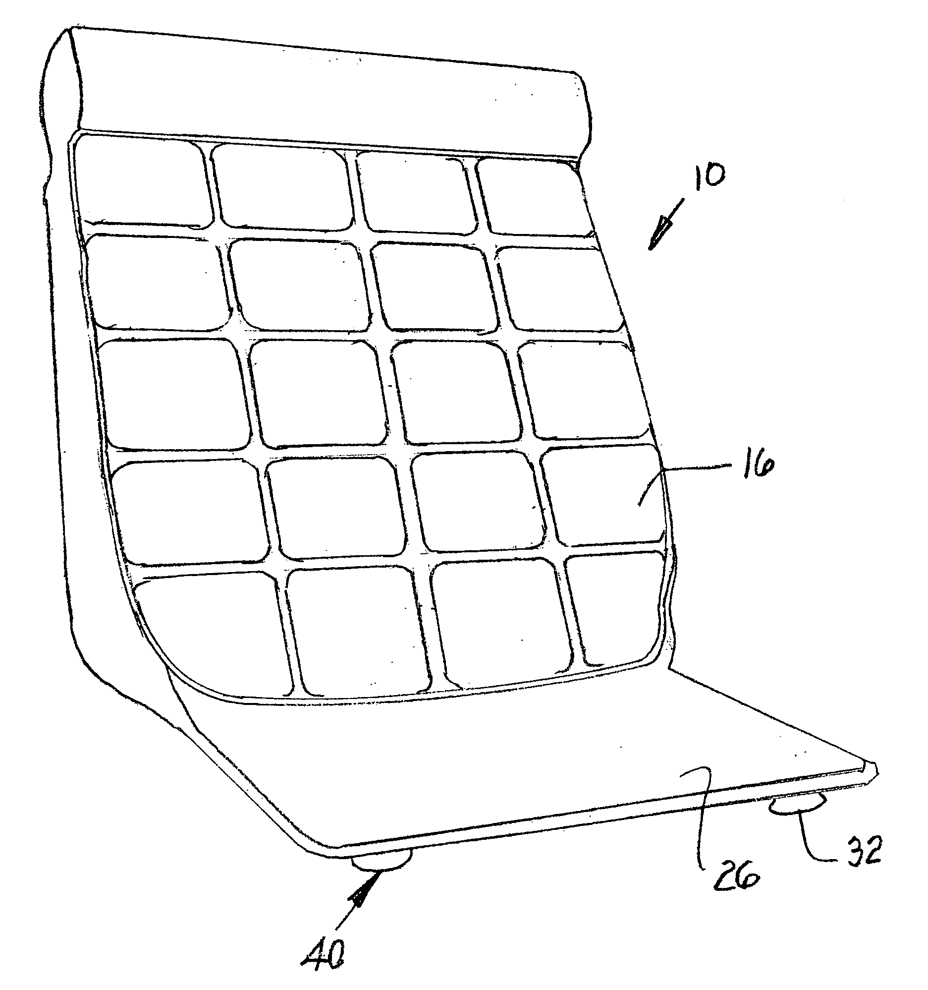
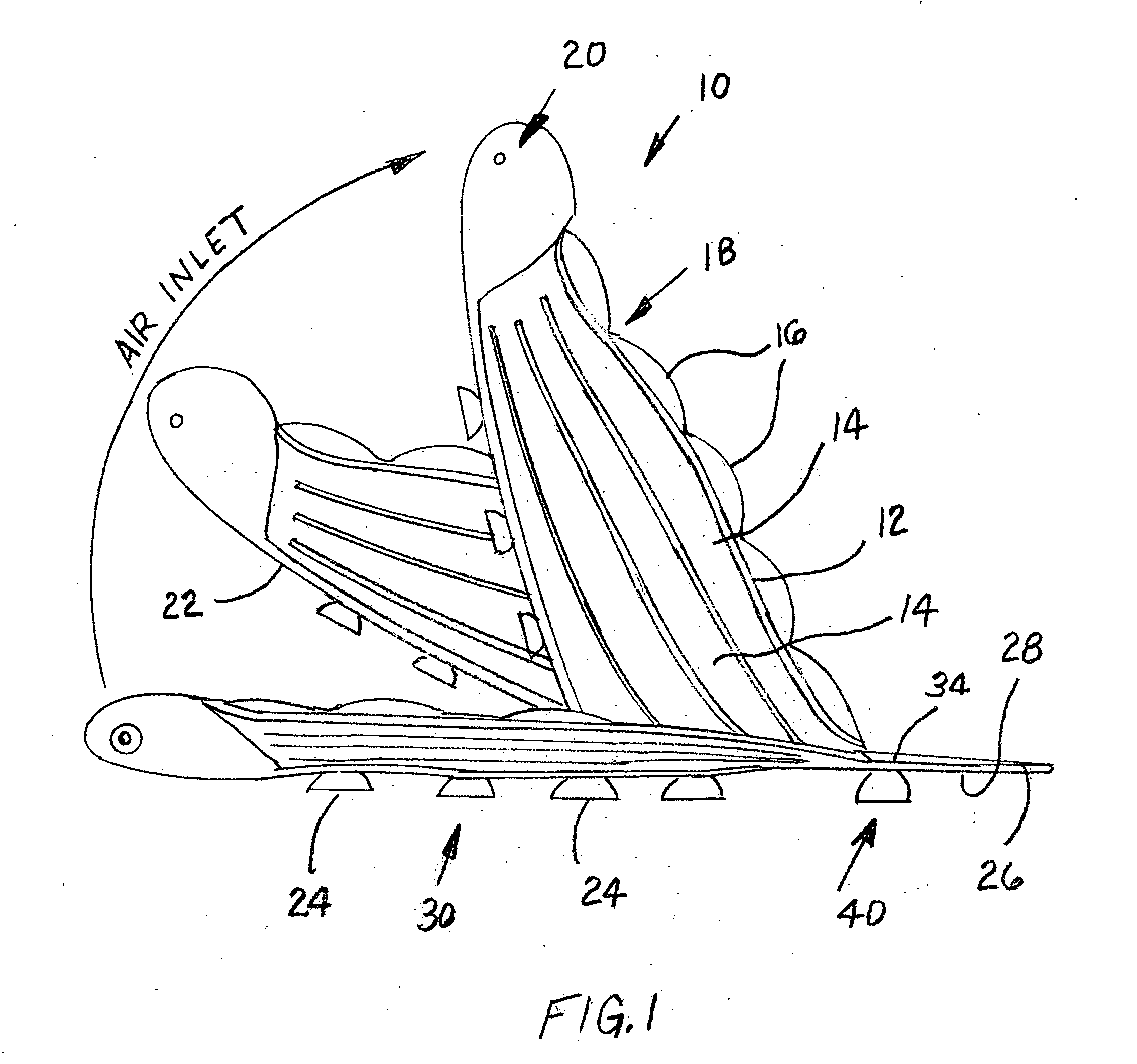
[0014]FIG. 1 is a side elevation view of a presently preferred embodiment of the bath tub cushion manufactured according to the instant invention; and

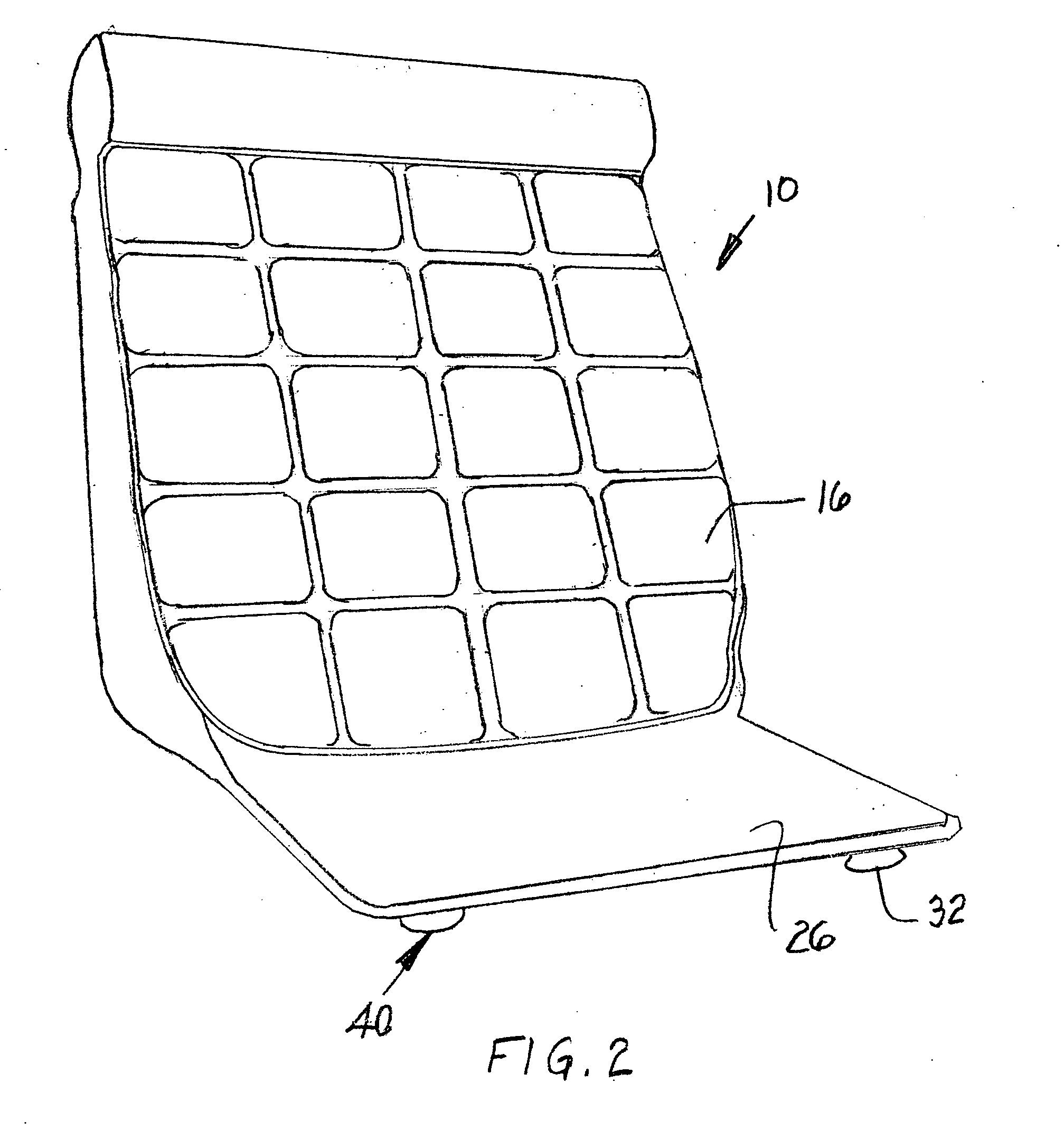
[0015]FIG. 2 is a perspective view of the bath tub cushion illustrated in FIG. 1.

BRIEF DESCRIPTION OF A PRESENTLY PREFERRED AND VARIOUS ALTERNATIVE EMBODIMENTS OF THE INVENTION

[0016]Prior to proceeding to the more detailed description of the present invention it should be noted that, for the sake of clarity and understanding, identical components which have identical functions have been identified with identical reference numerals throughout the several views illustrated in the drawing figures.

[0017]Reference is now drawn, more particularly, to the drawing FIGS. 1 and 2. Illustrated therein is a bath tub cushion, generally designated 10, for lining at least one end surface (not sh...


PUM


Abstract

A bath tub cushion for lining one end surface and a portion of a bottom surface of a bath tub includes a back portion having a number of fluid impermeable chambers formed therein. A fluid communication device is disposed in fluid communication with an interior portion of the chambers for inflating and deflating them as necessary. An anti-slip mechanism is disposed on a back surface of the back portion which engages an end of such bath tub to prevent movement during use. A bottom portion extends toward an opposed end of such tub and is connected to a bottom edge of a front portion of such back portion for supporting a person's hips during bathing. There is an additional anti-slip mechanism disposed on a bottom surface of the bottom portion which engages bottom surface of such bath tub for preventing movement of the bottom portion during use.

Description

CROSS REFERENCE TO RELATED APPLICATION[0001]This patent application is related to and claims priority from U.S. Provisional Patent Application Ser. No. 60 / 876,009 filed Dec. 20, 2006.FIELD OF THE INVENTION[0002]The present invention relates, in general, to bathtubs and, more particularly, this invention relates to an apparatus disposable in a bathtub to greatly enhance the comfort of a person taking a bath therein.BACKGROUND OF THE INVENTION[0003]Prior to the conception and development of the present invention, as is generally well known in the prior art, bathtubs can be quiet uncomfortable to sit in for any extended period of time due to the hardness of the ceramic or plastic tub. This is particularly the case for the elderly persons and persons who are relatively thin and have less padding on their hips.[0004]There have been prior attempts to solve this problem as is evidenced in the prior art. See, for example, U.S. Pat. No. 7,140,056 which teaches an inflatable pillow having a s...

Claims


Application Information

Patent Timeline
Patent Type & Authority Applications(United States)
IPC IPC(8): A47K3/022A47K3/02A47K3/06
CPCA47K3/125
Inventor CLINE, MARYANNCLINE, DAVID
Owner CLINE MARYANN
Why Eureka
Try Eureka