Composite module
- Summary
- Abstract
- Description
- Claims
- Application Information
AI Technical Summary
Problems solved by technology
Method used
Image
Examples
first embodiment
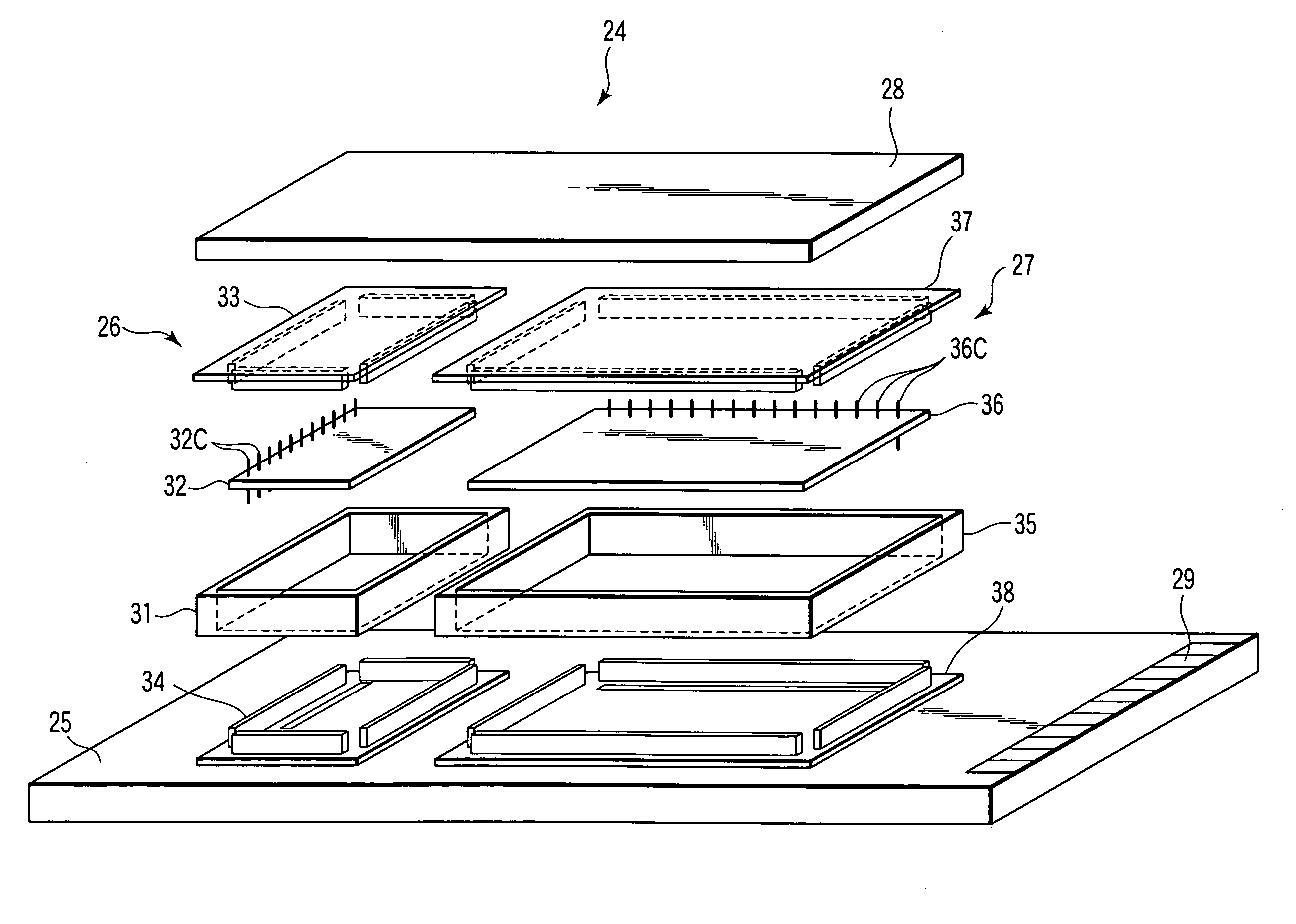
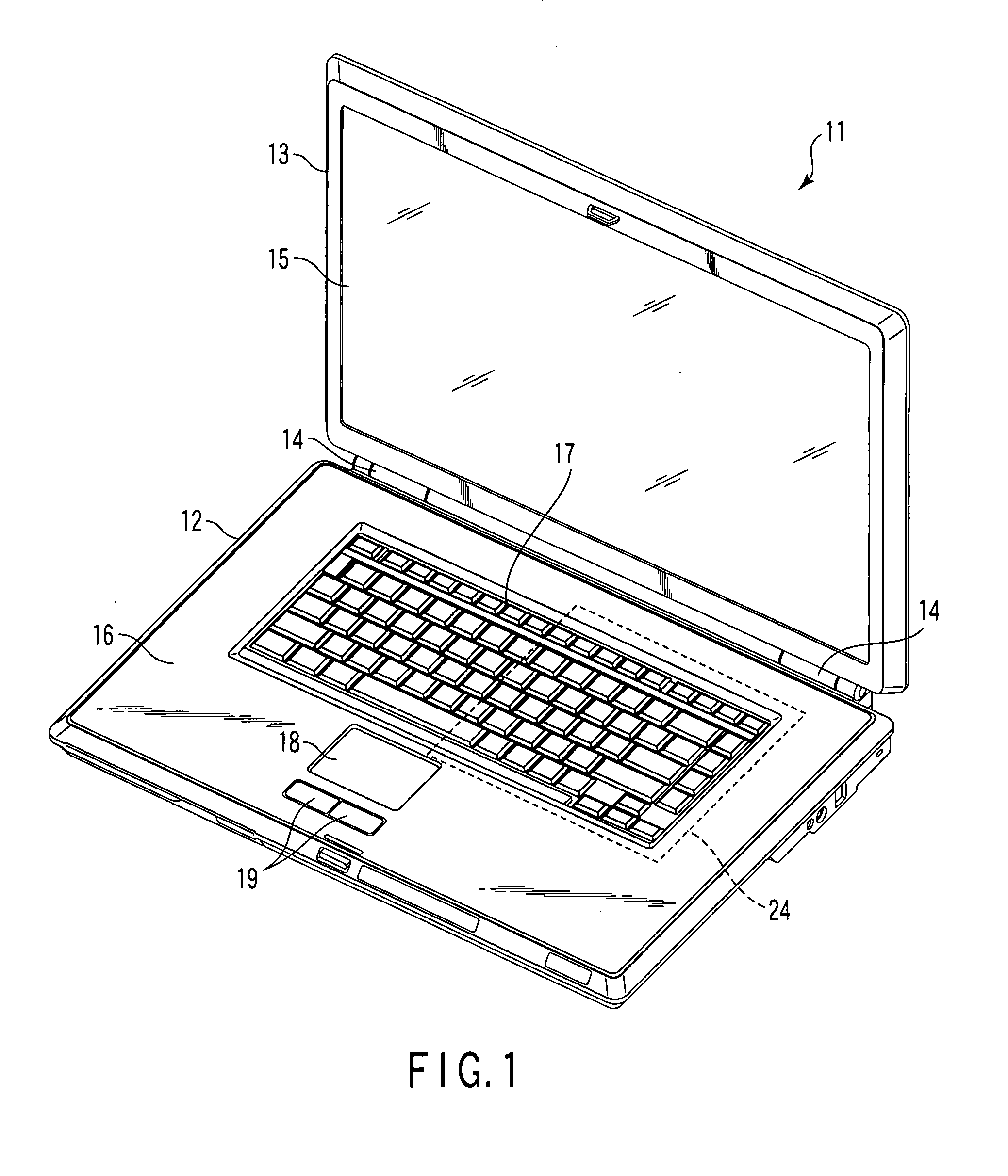
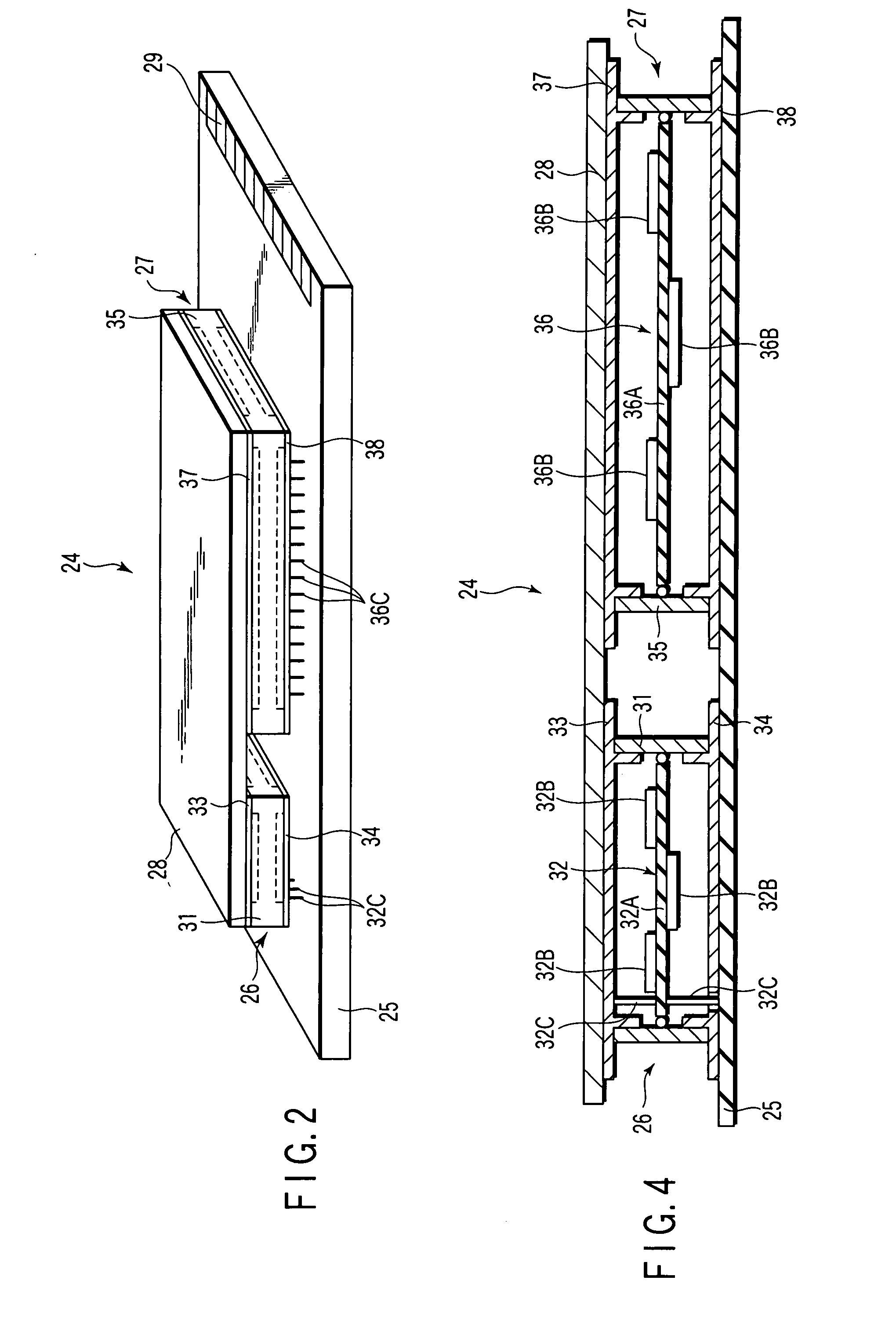
[0031]Up to here, the portable computer 11 has been described. According to this embodiment, the composite module 24 is thermally connected to both of the first module 26 and the second module 27, and it includes the heat radiating plate 28 that radiates the heat of these to the outside. With this structure, the heat radiating plate 28 serves to radiate the heat of the first module 26 and that of the second module 27, and also to thermally connect the first module 26 and the second module 27 to each other. Therefore, for example, when the first module 26 is generating heat, the heat is released to the heat radiating plate 28 and the second module 27 to equalize the temperatures of the modules. Thus, the first module 26 is cooled down. On the other hand, when the second module 27 is generating heat, the heat is released to the heat radiating plate 28 and the first module 26 to equalize the temperatures of the modules. Thus, the second module 27 is cooled down.
[0032]In this case, the ...
second embodiment
[0036]As shown in FIG. 5, the composite module 41 of the second embodiment includes a substrate 25, a first module 26 mounted on the substrate 25, a second module 27 mounted on the substrate 25 such as to be independent from the first module 26, a heat conductive sheet 42 that thermally connects the first module 26 and the second module 27 to each other, a first heat radiating plate 43 fixed to an upper side of the heat conductive sheet 42 such as to be overlaid on the first module 26, and a second heat radiating plate 44 fixed to an upper side of the heat conductive sheet 42 such as to be overlaid on the second module 27.
[0037]The heat conductive sheet 42 is made of, for example, a carbon graphite sheet and has a high thermal conductivity. The heat conductive sheet 42 includes a first end portion 42A overlaid on the first module 26 and a second end portion 42B overlaid on the second module 27. The heat conductive sheet 42 is able to thermally connect the first module 26 and the sec...
third embodiment
[0049]As shown in FIG. 5, the composite module 51 of the third embodiment includes a substrate 25, a first module 26 mounted on the substrate 25, a second module 27 mounted on the substrate 25 such as to be independent from the first module 26, a heat conductive sheet 52 that thermally connects the first module 26 and the second module 27 to each other, a first heat radiating plate 43 fixed to an upper side of the heat conductive sheet 52 such as to be overlaid on the first module 26, and a second heat radiating plate 44 fixed to an upper side of the heat conductive sheet 52 such as to be overlaid on the second module 27.
[0050]The heat conductive sheet 52 is made of, for example, a copper foil and has a high thermal conductivity and a high electro-conductivity. The heat conductive sheet 52 includes a first end portion 52A overlaid on the first module 26, a second end portion 52B overlaid on the second module 27, and an intermediate portion 52C having a shape of bellows. The heat con...
PUM
 Abstract
Description
Claims
Application Information
 - R&D
- Intellectual Property
- Life Sciences
- Materials
- Tech Scout
- Unparalleled Data Quality
- Higher Quality Content
- 60% Fewer Hallucinations
Browse by: Latest US Patents, China's latest patents, Technical Efficacy Thesaurus, Application Domain, Technology Topic, Popular Technical Reports.
© 2025 PatSnap. All rights reserved.Legal|Privacy policy|Modern Slavery Act Transparency Statement|Sitemap|About US| Contact US: help@patsnap.com


