Implementation of a wireless power transmitter and method

a wireless power transmitter and wireless technology, applied in the direction of electromagnetic wave systems, circuit arrangements, lighting and heating apparatus, etc., can solve the problems of unsatisfactory lifetime cost and maintenance requirements of applications, unscheduled maintenance trips are even more costly and disruptive, and many devices do not provide the lifetime cost and maintenance requirements for applications

Inactive Publication Date: 2008-07-17
POWERCAST
View PDF3 Cites 351 Cited by
  • Summary
  • Abstract
  • Description
  • Claims
  • Application Information

AI Technical Summary

Problems solved by technology

Even with power conscious designs and the latest in battery technology, many devices do not provide the lifetime cost and maintenance requirements for applications that require a large number of untethered devices such as logistics and building automation.
For both device types, scheduled power-source maintenance is costly

Method used


Image

  • Implementation of a wireless power transmitter and method
  • Implementation of a wireless power transmitter and method
  • Implementation of a wireless power transmitter and method

Examples


Embodiment Construction

[0026]A complete understanding of the invention will be obtained from the following description when taken in connection with the accompanying drawing figures wherein like reference characters identify like parts throughout.

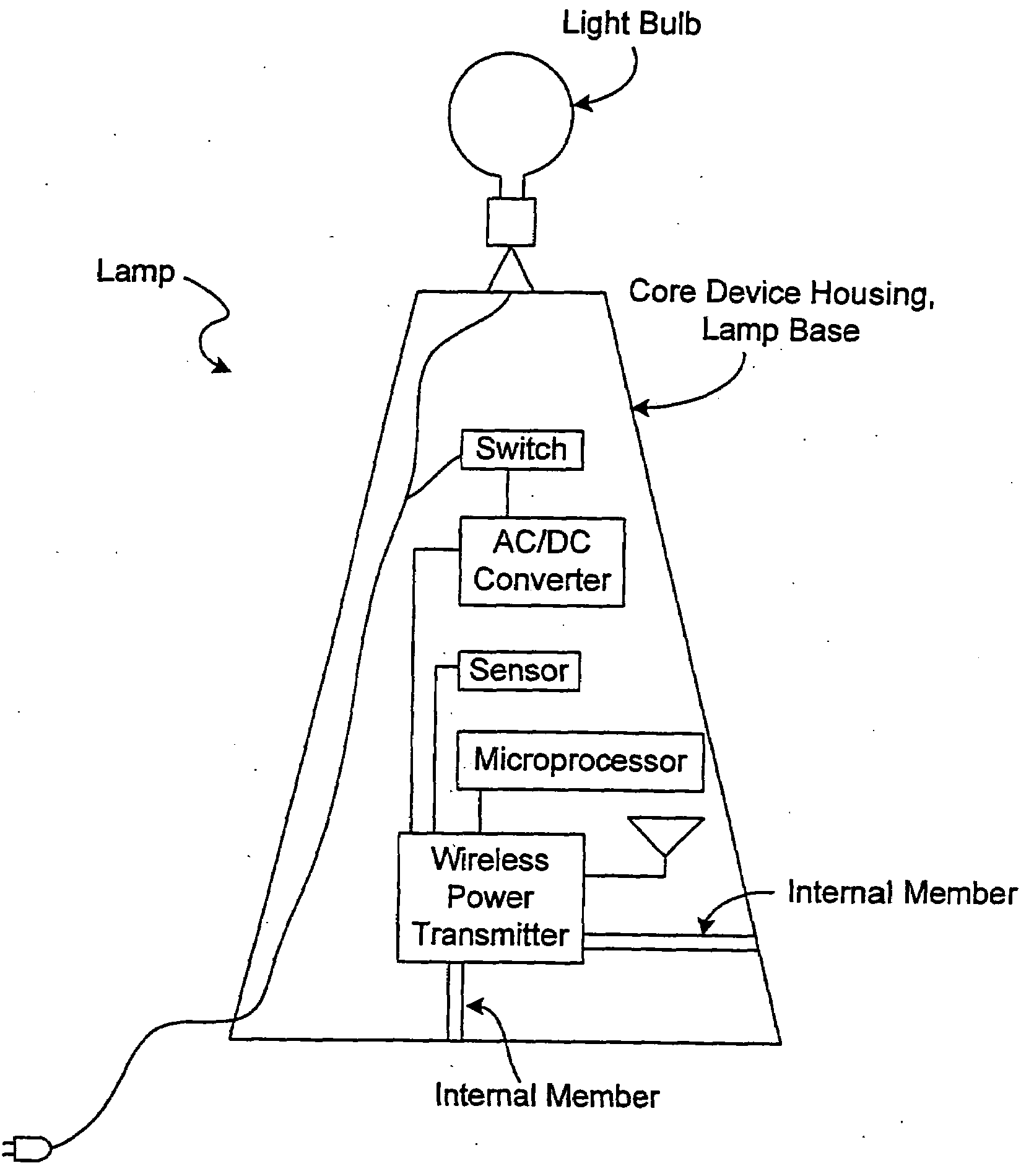
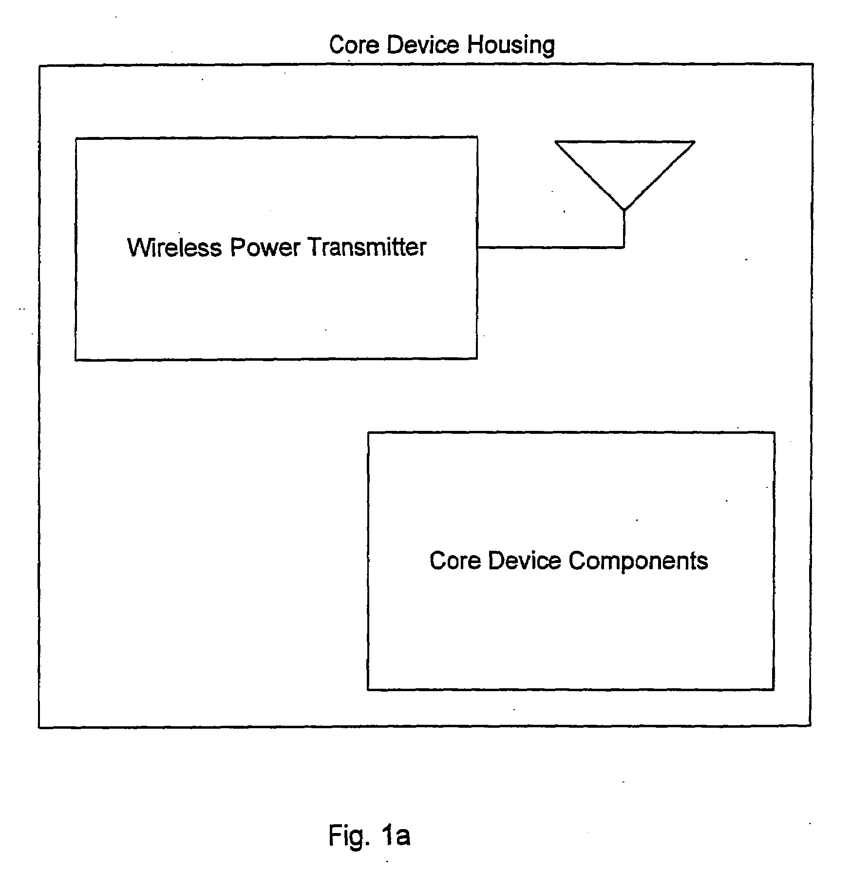
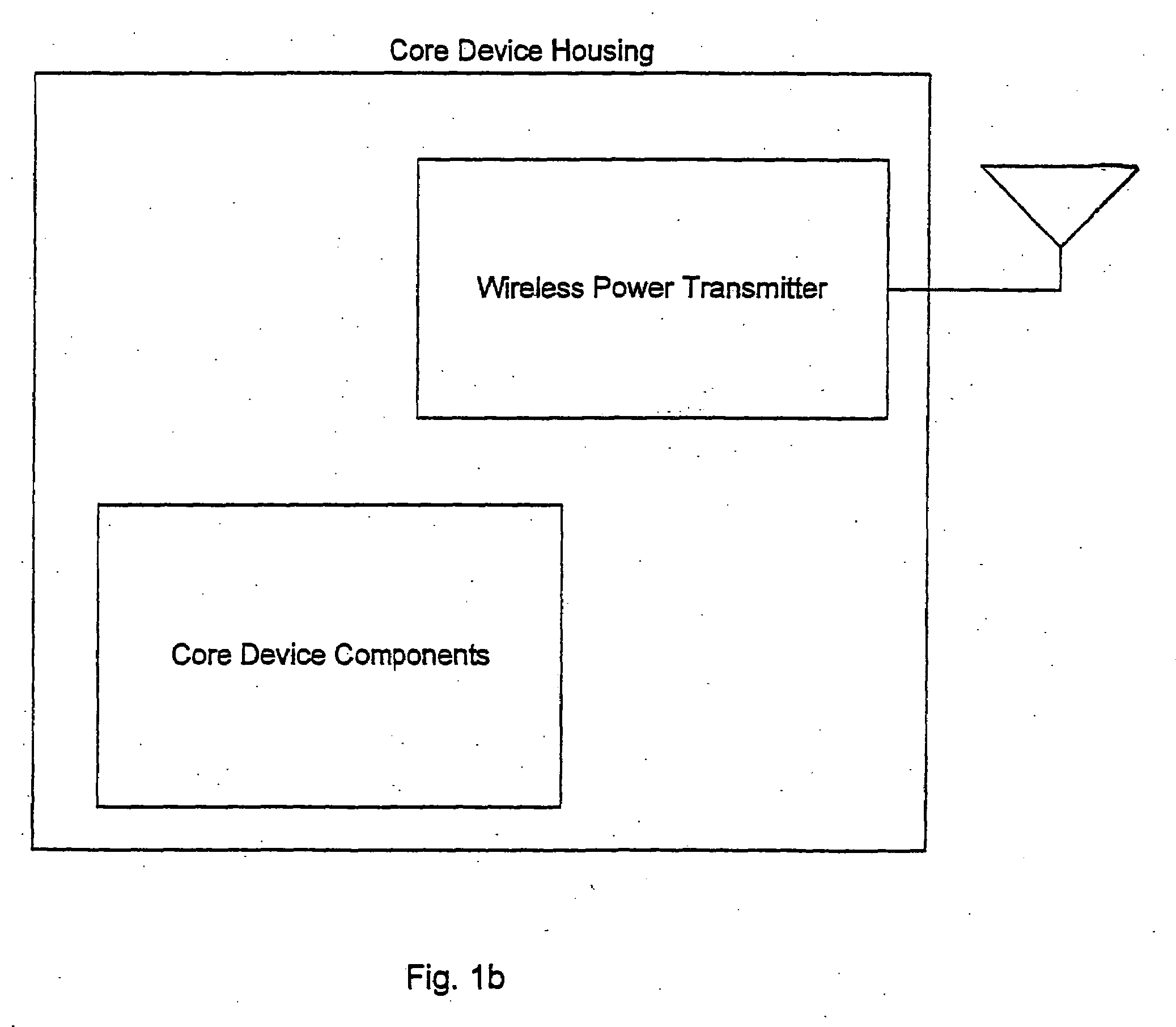
[0027]The present invention pertains to a device 10 for a particular purpose. The device 10 comprises a housing 12. The device 10 comprises a wireless power transmitter 14 connected to the housing 12, wherein the wireless power transmitter 14 sends wireless power, and the particular purpose is not sending wireless power.

[0028]The wireless power transmitter 14 can be either inside or outside the housing 12. The device 10 can further include an antenna 16 connected to the wireless power transmitter 14. The antenna 16 can be inside or outside the housing 12. The transmitter 14 can send wireless power in pulses.

[0029]The device 10 can further including core device components 18 inside the housing 12. The wireless power transmitter 14 can share one or more of the core...


PUM


Abstract

Disclosed is a device for a particular purpose. The device includes a housing. A wireless power transmitter is connected to the housing. The wireless power transmitter sends wireless power. The particular purpose is something other than sending wireless power. A method for a particular purpose.

Description

FIELD OF THE INVENTION[0001]The present invention is related to the implementation of a wireless power transmitter. More specifically, the present invention is related to the wireless powering of target devices within the peripheral of a wireless power transmitter implemented in conjunction with a source device, apparatus, or structure (collectively “devices”).BACKGROUND OF THE INVENTION[0002]As processor capabilities have expanded and power requirements have decreased there has been an ongoing explosion of devices that operate completely independent of wires or power cords. These “untethered” devices range from cell phones and wireless keyboards to building sensors and active RFID tags. Engineers and designers of these untethered devices continue to have to deal with the limitations of portable power sources, primarily batteries as the key design parameter. While performance of processors and portable devices has been doubling every 18-24 months driven by Moore's law, battery techn...

Claims


Application Information

Patent Timeline
IPC IPC(8): H04Q5/22
CPCH02J17/00F21V23/0435H02J50/20H02J50/70H02J50/005
Inventor GREENE, CHARLES E.HARRIST, DANIEL W.MCELHINNY, MICHAEL THOMAS
Owner POWERCAST
Why Eureka
Try Eureka