Neck brace

a neck brace and neck technology, applied in the field of neck braces, can solve the problems of wearer's need to tilt the head more severely, and achieve the effect of inhibiting excessive neck movement and high degree of head movement of wearer

Inactive Publication Date: 2008-07-24
LEATT
View PDF6 Cites 11 Cited by
  • Summary
  • Abstract
  • Description
  • Claims
  • Application Information

AI Technical Summary

Benefits of technology

[0007]One or more embodiments of the invention inhibit excessive neck movement during impact, yet

Problems solved by technology

However, in some exceptional cases, notably in high speed road motorcycling, the wearer needs t

Method used


Image

  • Neck brace
  • Neck brace
  • Neck brace

Examples


Embodiment Construction

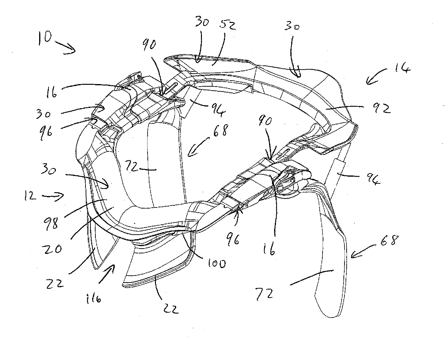
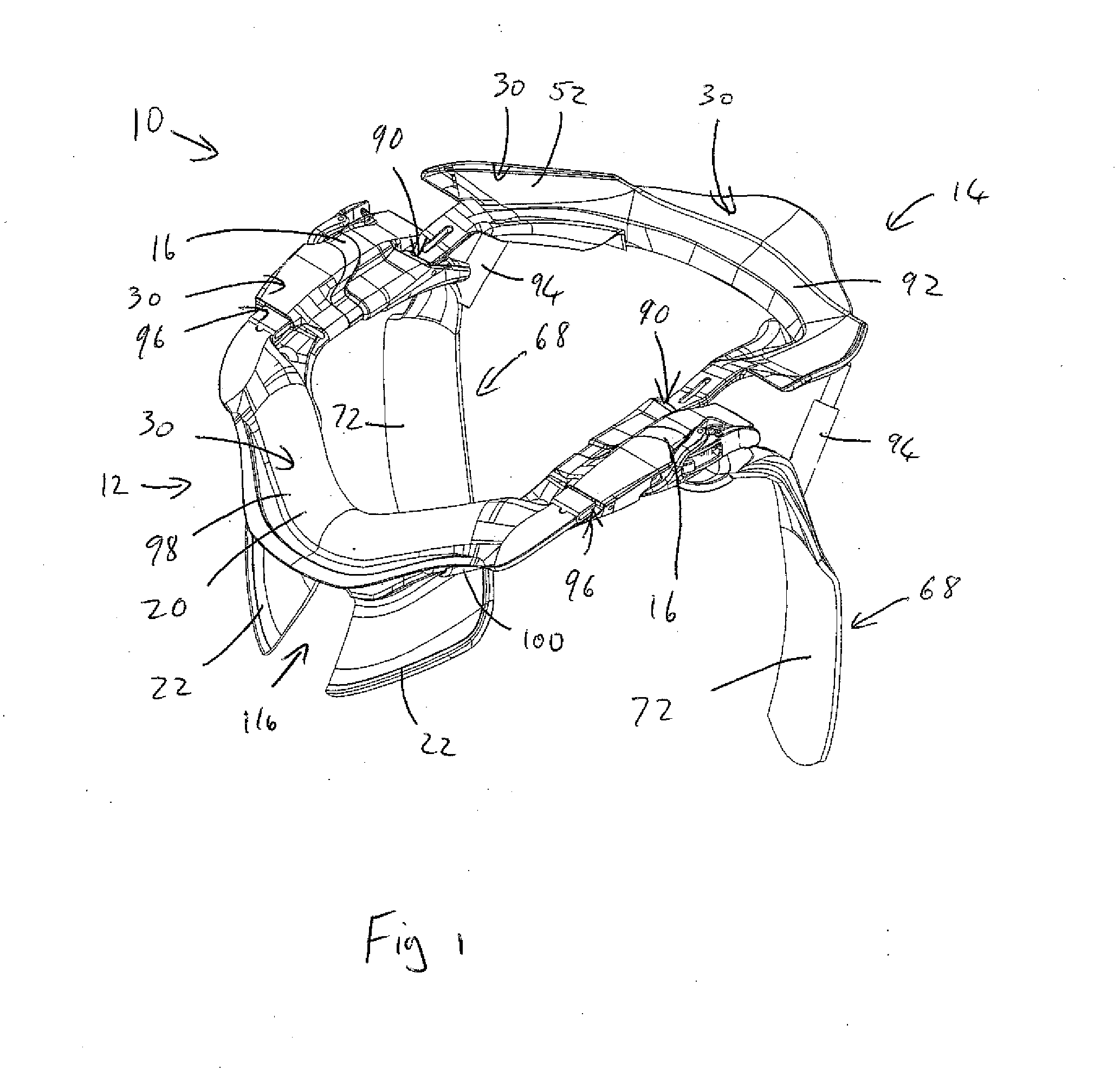
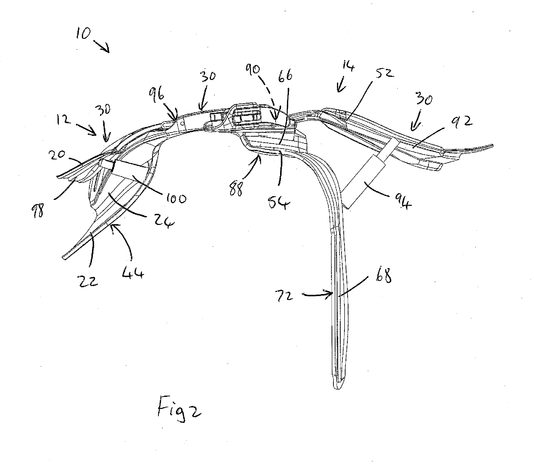
[0027]Referring to FIGS. 1 to 3, a neck brace in accordance with the present invention is generally indicated by reference numeral 10.

[0028]The neck brace 10 includes a front section 12 and a rear section 14 which can be secured together at lateral hinge connectors 16 to form a ring that can extend around the neck of a wearer. The front section 12 is U-shaped in plan view and includes a top flange 20 defining part of a generally upwardly facing impact surface 30 that can receive impact loads from the bottom of a full face helmet worn by the wearer, a bottom flange 22 defining a cushioned chest bearing surface 44 that is configured to bear on the wearer's chest, and a structure in the form of a wall 24 that extends between the top and bottom flanges to transfer the impact loads from the helmet to the wearer's body.

[0029]The rear section 14 is also U-shaped in plan view and includes a top flange 52 that is generally a continuation of the top flange 20 of the front section, with an upw...


PUM


Abstract

Neck brace that inhibits excessive neck movement during impact, yet allows for a high degree of movement of the wearer's head during normal operation of the neck brace. May include impact surface(s) that limits movement of a helmet by contacting an underside of the helmet; bearing surface(s) configured for bearing on wearer; a structure between impact surface and bearing surface, sufficiently resilient to transfer impact loads of the helmet to the impact surface, to the wearer's body; wherein the impact surface is displaceable towards an adjacent part of the bearing surface and wherein the structure is configured to permit the displacement at rates slower than a predetermined rate of displacement and to resist the displacement if the rate of displacement exceeds the predetermined rate. May include a pivotal joint between the displaceable part and remainder of neck brace and impact brake element(s).

Description

[0001]This application is continuation in part of U.S. Utility patent application Ser. No. 11 / 440,576 which is a national stage filing of international application PCT / ZA2004 / 000148 filed 26 Nov. 2004, published in English under PCT Article 21(2), which claims benefit from and is a Paris Convention filing of South African Patent Application Serial No. 2003 / 9174 filed 26 Nov. 2003, the specifications of which are all hereby incorporated herein by reference.BACKGROUND OF THE INVENTION[0002]1. Field of the Invention[0003]This invention relates to protective equipment for inhibiting neck injuries while wearing a helmet. In particular, the invention relates to a neck brace.[0004]2. Description of the Related Art[0005]A device in the form of a neck brace is disclosed in International Patent Application No. PCT / ZA04 / 00148, which is intended to be worn around the neck and to receive impact loads from the bottom edge of a full face helmet and to transfer these loads to the wearer's body alon...

Claims


Application Information

Patent Timeline
IPC IPC(8): A61F5/00
CPCA41D13/0512A61F5/055A42B3/0473A41D2600/102Y10S128/23
Inventor LEATT, CHRISTOPHER JAMESNELSON, GRANT LEIGHHOPKINS, MARK ERIC
Owner LEATT
Why Eureka
Try Eureka