Paint Reservoir System For A Paint Spray Gun

Active Publication Date: 2008-07-31
SATA GMBH & CO KG
View PDF13 Cites 42 Cited by
  • Summary
  • Abstract
  • Description
  • Claims
  • Application Information

AI Technical Summary

Benefits of technology

[0004]Starting with these disadvantages associated with the known flow reservoirs, the invention is based on the task of presenting a paint spray gun paint reservoir system that enables a simple

Problems solved by technology

Such a tool is often not available.
Furthermore, puncturing the container wall, which is generally made from hard plastic, with a suitable pointed tool has also proven to

Method used


Image

  • Paint Reservoir System For A Paint Spray Gun
  • Paint Reservoir System For A Paint Spray Gun
  • Paint Reservoir System For A Paint Spray Gun

Examples


Embodiment Construction

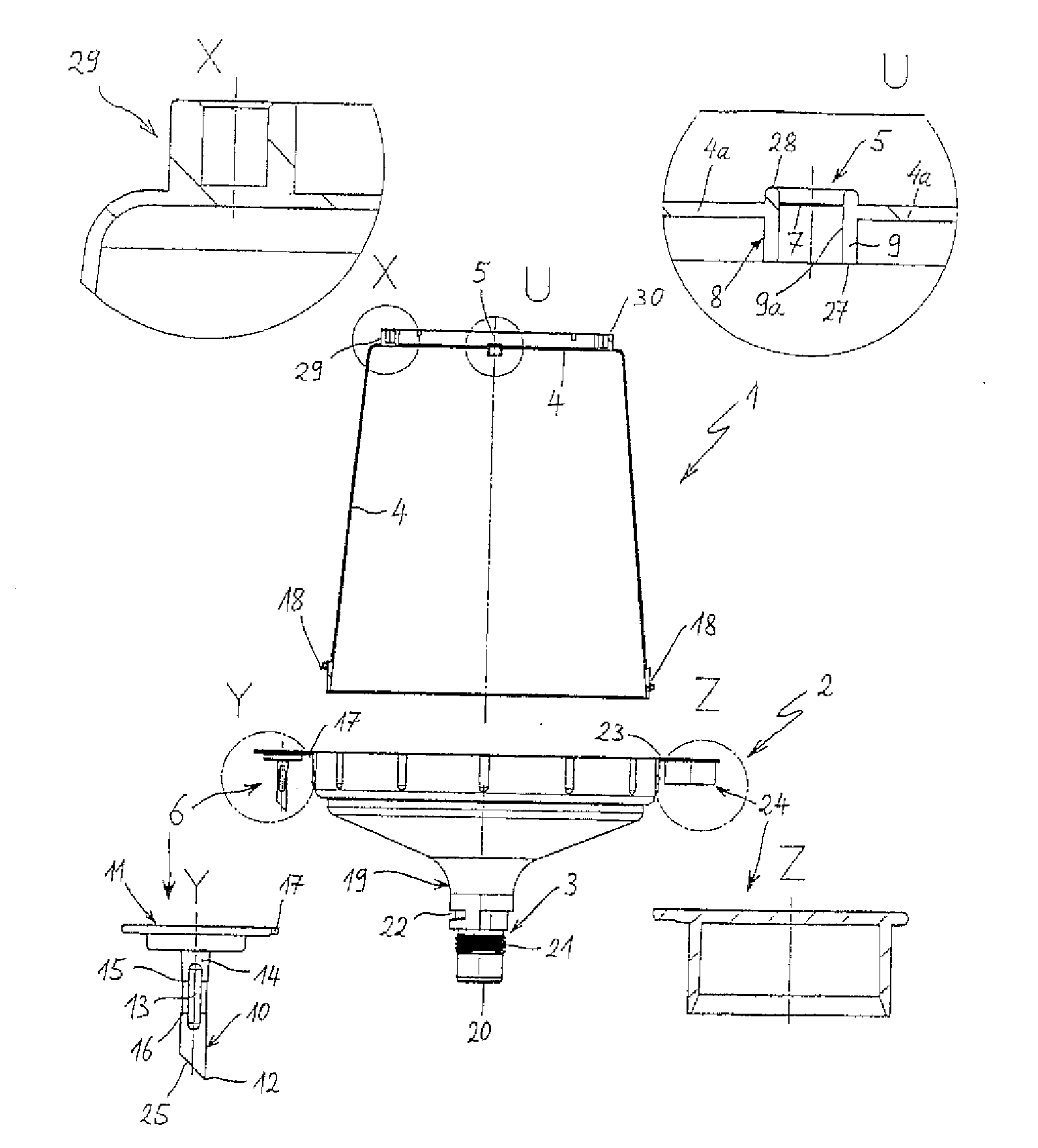
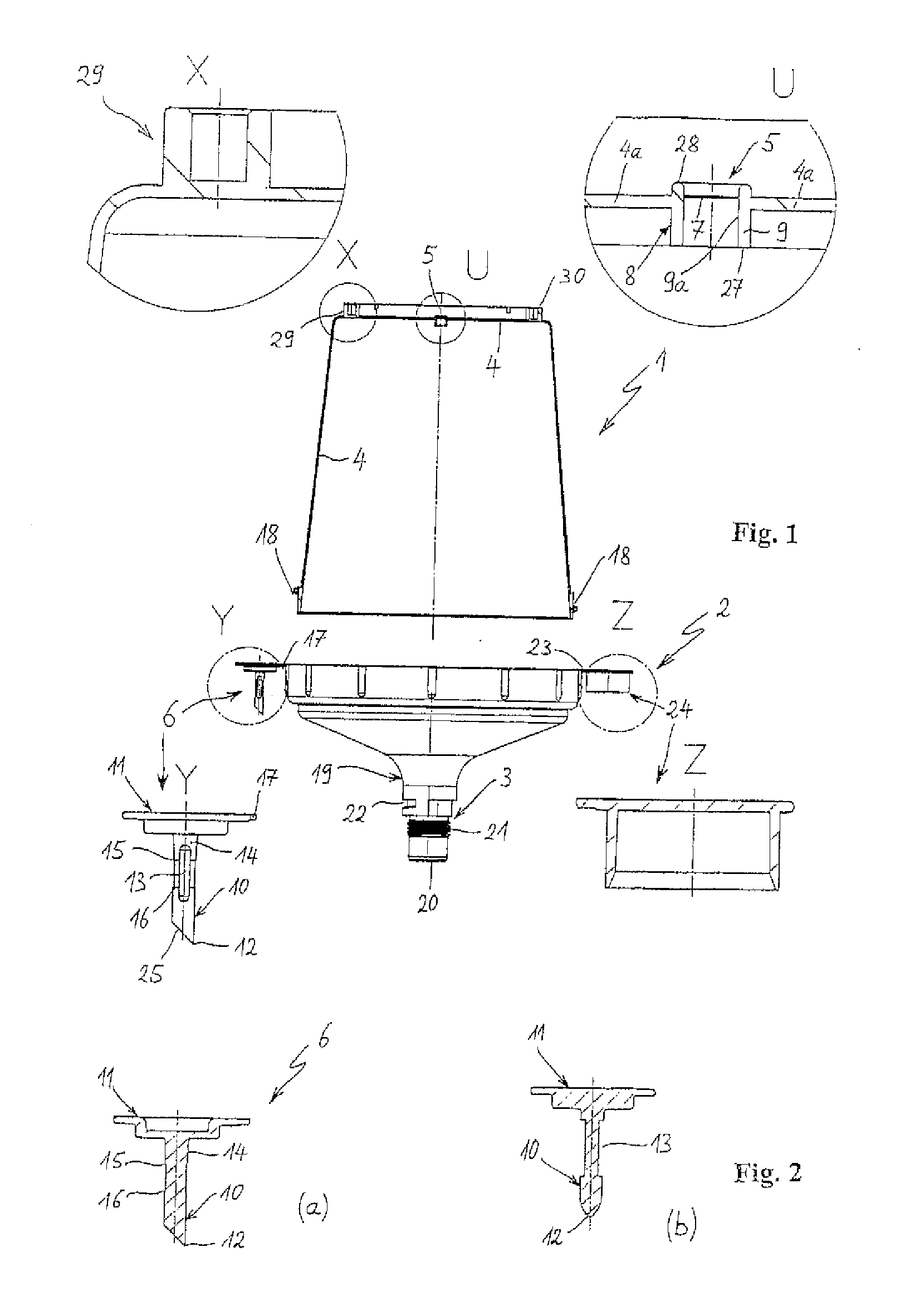
[0010]In FIG. 1, a flow reservoir for a paint spray gun is shown that includes a container 1 and a cover 2 that can be screwed onto the container by means of a thread 18. Here, the flow reservoir is shown in FIG. 1 in the position in which the flow reservoir is set on the paint spray gun, thus with the top side of the cover 2 pointing downwards. The cover 2 has an outlet port 19 with an outlet opening 20 in its top side. An attachment part 3 is formed on the outer side of the outlet port 19. The attachment part 3 is used for setting and fastening the flow reservoir on a paint spray gun, or on an adapter arranged between the paint spray gun and the flow reservoir. In the embodiment shown in FIG. 1, the attachment part 3 includes a thread 21 and a wedge-shaped groove 22, which interacts with corresponding attachment parts of the paint spray gun, namely a corresponding internal thread and a peg for engaging in the groove 22.

[0011]The container 1 is bowl-shaped with a circular container...


PUM

PropertyMeasurementUnit
Lengthaaaaaaaaaa
Distanceaaaaaaaaaa

Abstract

The invention relates to a gravity flow reservoir for a paint spraying gun having a container and a cover, which can be placed thereon and which has a connecting part in order to place the gravity flow reservoir onto the paint spraying gun or onto an adapter. Prior art reservoirs require a separate pointed tool, which serves to make a vent hole, is often unavailable and can lead to operating errors. The aim of the invention is to provide a paint reservoir system that enables a simple, rapid and uncomplicated insertion of a vent hole into the container wall of the gravity flow reservoir while preventing shavings or plastic parts from entering the gravity flow reservoir. To this end, a delimited area is provided in the wall of the container and can be penetrated by the pointed tool in order to make a vent hole.

Description

FIELD OF THE INVENTION[0001]The invention relates to a flow reservoir for a paint spray gun, to a pointed tool, especially a spike, for puncturing a ventilation opening in the wall of a paint spray gun paint reservoir and to a paint reservoir system consisting of a flow reservoir and a pointed tool.BACKGROUND OF THE INVENTION[0002]Flow reservoirs are known from the prior art, e.g., U.S. Pat. No. 6,536,687 B1 and FR 2 774 928-A. These include a container made from plastic and a cover that can be placed on the container for closing the container. There are attachment means on the top side of the cover for setting and fastening the flow reservoir on a paint spray gun. Here, the flow reservoir is set on the paint spray gun “upside-down,” thus with the cover side pointing downwards. The paint in the flow reservoir then flows downwards, due to gravity, into the paint inlet channel of the paint spray gun. To enable the gravity fed flow of the paint, the pressure within the paint reservoir ...

Claims


Application Information

Patent Timeline
IPC IPC(8): B05B7/24B26F1/00B67D3/00
CPCB05B7/2478B05B7/2408
Inventor SCHMON, EWALDDETTLAFF, PETER
Owner SATA GMBH & CO KG
Why Eureka
Try Eureka