Moving image encoding device and moving image encoding method

a moving image and encoding technology, applied in signal generators with optical-mechanical scanning, color televisions with bandwidth reduction, signal systems, etc., can solve problems such as inefficiency of device configuration, reference image information, and motion vector information based only on one component not necessarily optimal methods, so as to increase the connectability of video encoded data

Inactive Publication Date: 2008-07-31
MITSUBISHI ELECTRIC CORP
View PDF6 Cites 63 Cited by
  • Summary
  • Abstract
  • Description
  • Claims
  • Application Information

AI Technical Summary

Benefits of technology

[0006]It is therefore an object of the present invention to provide a bit stream generation method for providing compatibility between a bit stream encoded in a Y, Cb, and Cr space as in the case of the conventional 4:2:0 format and a bit stream having no sample ratio distinction between color components such as the 4:4:4 format and obtained by compressing a video signal having freedom in color space definition, and a decoding method.
[0008]Encoding / decoding can be performed for the plurality of different chroma formats such as 4:2:0, 4:2:2, and 4:4:4 in a unified manner by the efficient device configuration, and mutual connectability between the video encoded data can be increased.

Problems solved by technology

The system for performing motion compensation prediction based on inter prediction mode, reference image information, and motion vector information depending only on one component is not necessarily an optimal method in the 4:4:4 format where the color components make equal contributions in representing a structure of an image signal.
As a result, to construct a decoding device capable of decoding compressed video data of a plurality of different formats, a configuration where bit streams for signals of the formats are individually interpreted needs to be employed, thereby making a device configuration inefficient.

Method used


Image

  • Moving image encoding device and moving image encoding method
  • Moving image encoding device and moving image encoding method
  • Moving image encoding device and moving image encoding method

Examples


first embodiment

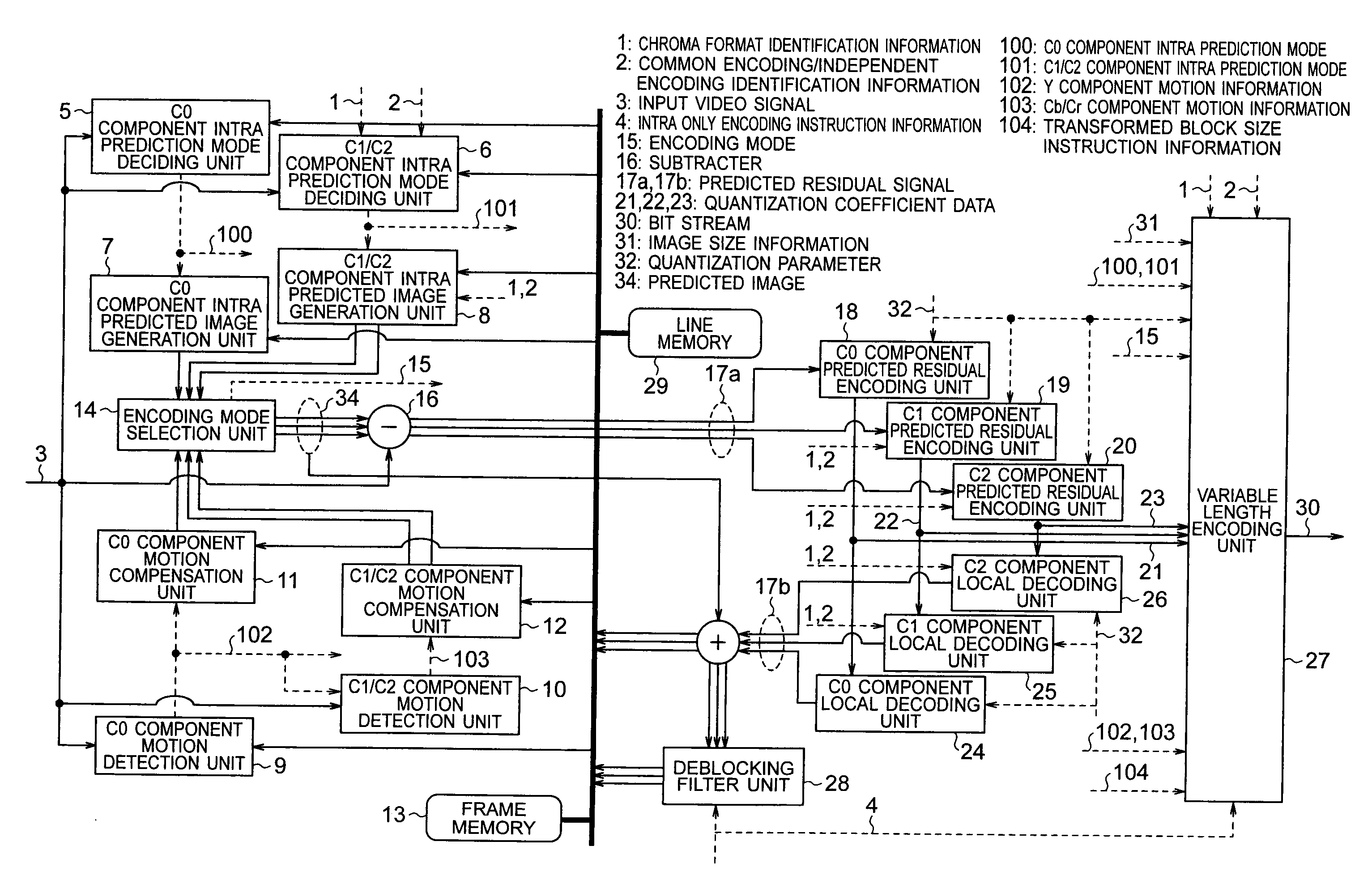
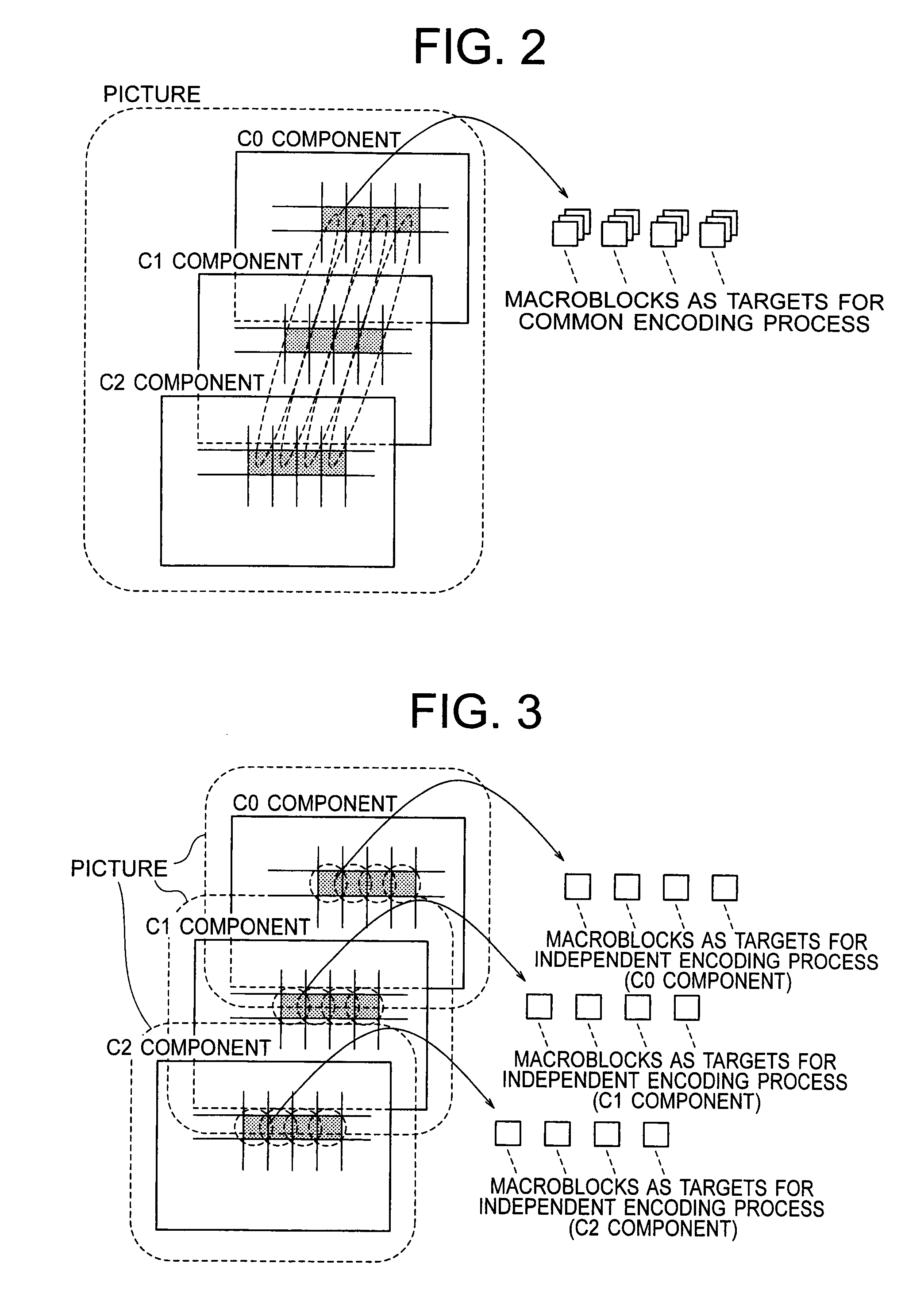
[0033]A first embodiment of the present invention relates to an encoding device which receives one of a video signal of a chroma format of 4:2:0 or 4:2:2 defined in a (Y, Cb, and Cr) color space and a video signal of a chroma format of 4:4:4 defined in a (R, G, and B), (Y, Cb, and Cr), or (X, Y, and Z) color space to perform video encoding, and outputs a bit stream, and a decoding device which receives the encoded bit stream generated by the encoding device to restore an image signal. In the description below, three color components will generically be referred to as (C0, C1, and C2) components and, in the case of 4:2:0 and 4:2:2 chroma formats, C0, C1, and C2 components will be regarded as a Y component, a Cb component, and a Cr component, respectively.

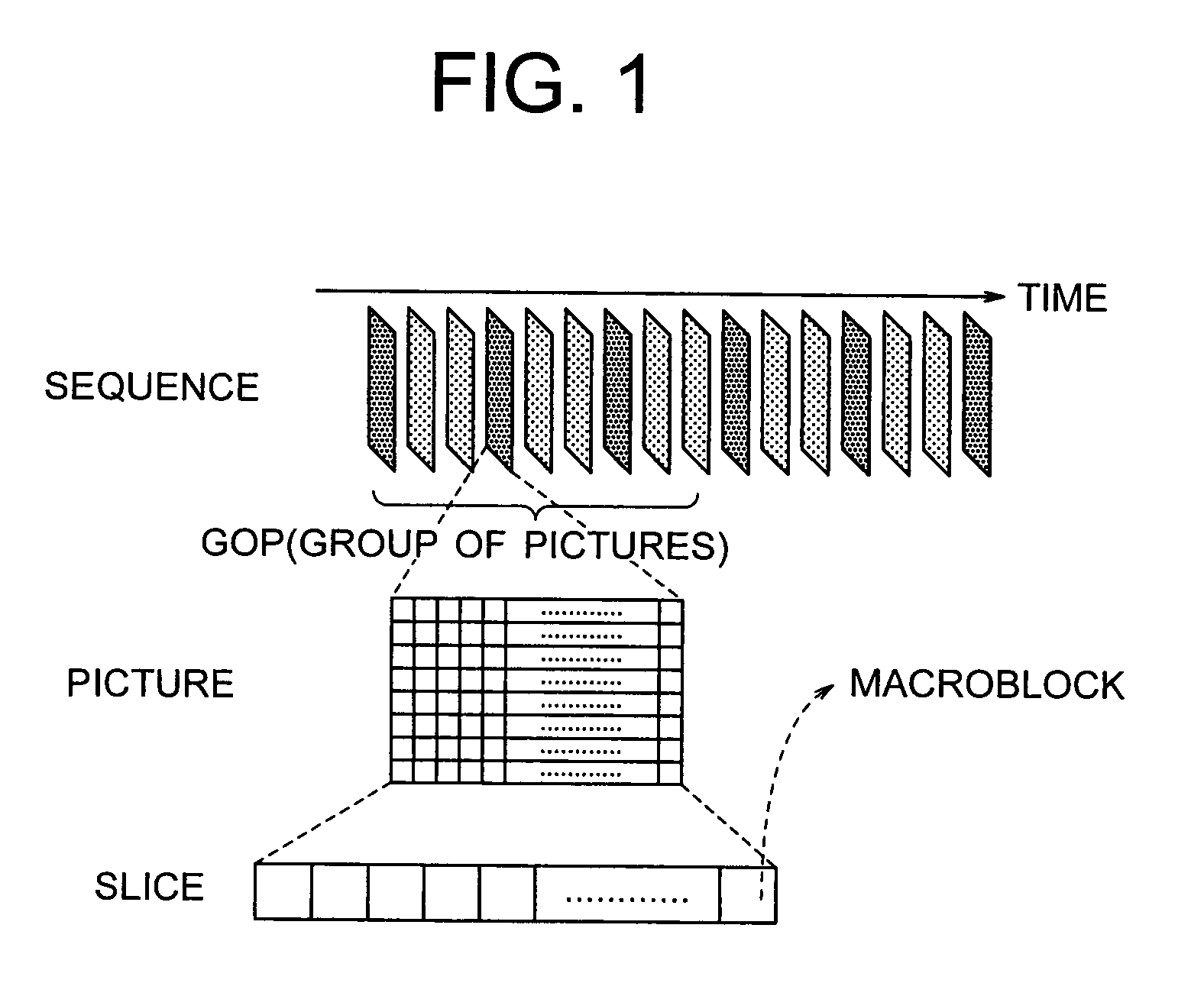
[0034]As shown in FIG. 1, the encoding device of the first embodiment of the present invention receives a video signal represented as time-sequential data of screen information (hereinafter, called picture) defined by a frame or fiel...


PUM


Abstract

Encoding and decoding are uniformly carried out for a plurality of chroma formats. Based on a control signal for providing a chroma format type of an input moving image signal, in the case of a chroma format of 4:2:0 or 4:2:2, a first intra prediction mode deciding unit and a first intra prediction image generation unit are applied to a luminance component of the input moving image signal, and a second intra prediction mode deciding unit and a second intra prediction image generation unit are applied to a chrominance component. In the case of a chroma format of 4:4:4, the first intra prediction mode deciding unit and the first intra prediction image generation unit are applied to all color components to carry out encoding, and a variable length encoding unit multiplexes the control signal as encoding data to be applied to a moving image sequence unit on a bit stream.

Description

BACKGROUND OF THE INVENTION[0001]1. Field of the Invention[0002]The present invention relates to a digital image signal encoding device, a digital image signal decoding device, a digital image signal encoding method, and a digital image signal decoding method used for an image compression encoding technology or a compressed image data transmission technology.[0003]2. Description of the Related Art[0004]An international standard video encoding system such as MPEG or ITU-TH. 26x (e.g., “Information Technology Coding of Audio-Visual Objects Part 10: Advanced Video Coding”, ISO / IEC 14496-10, 2003: (hereinafter, referred to as Non-Patent Document 1)) has conventionally been premised on use of a standardized input signal format called a 4:2:0 format. The 4:2:0 format is a format where a color moving image signal of RGB or the like is transformed into a luminance component (Y) and two chrominance components (Cb, Cr), and the number of chrominance component samples is reduced to half of lum...

Claims


Application Information

Patent Timeline
Patent Type & Authority Applications(United States)
IPC IPC(8): H04N11/04H04N19/11H04N19/12H04N19/105H04N19/134H04N19/136H04N19/159H04N19/196H04N19/42H04N19/423H04N19/46H04N19/50H04N19/503H04N19/51H04N19/513H04N19/523H04N19/577H04N19/593H04N19/60H04N19/61H04N19/70H04N19/80H04N19/91
CPCH04N7/26H04N19/186H04N19/70H04N19/82H04N19/11H04N11/04
Inventor SEKIGUCHI, SHUNICHIMORIYA, YOSHIMISUGIMOTO, KAZUOYAMADA, YOSHIHISAASAI, KOHTAROMURAKAMI, TOKUMICHIIDEHARA, YUICHI
Owner MITSUBISHI ELECTRIC CORP
Why Eureka
Try Eureka