Calibration device and method for robot mechanism

a multi-jointed robot and calibration method technology, applied in the direction of instrumentation, electric controllers, program control, etc., can solve the problems of the inability to accurately judge the selection position and orientation of the robot, and the inability to accurately predict the calibration

Active Publication Date: 2008-08-07
FANUC LTD
View PDF12 Cites 67 Cited by
  • Summary
  • Abstract
  • Description
  • Claims
  • Application Information

AI Technical Summary

Benefits of technology

[0018]According to another aspect of the present invention, there is provided a method for calibrating a multi-jointed robot mechanism, comprising the steps of: carrying out an alignment in which the positional relationship between a first coordinate system fixed to a part of a robot and a second coordinate system fixed outside of the robot satisfies a predetermined condition; designating a position of the robot as an initial position, where the positional relationship between the first and second coordinate systems generally satisfies a predetermined condition, in order to carry out the alignment at a plurality of positions; automatically determining a plurality of preliminary positions for carry out the alignment, based on the designated initial position, the first coordinate system and a predetermined para

Problems solved by technology

Also, the accuracy of the calibration is greatly affected by the position and the orientation of the robot used for the measurement.
One major problem regarding the calibration in the industrial field is that the selected position and the orientation of the robot cannot be appropriately judged until a series of operations of the calibration have taken place, including measuring, correcting and evaluating.
In particular, when the position and the orientation of the robot empirically obtained cannot be used in the industrial field and the position and the orientation are changed corresponding to the environment of the industrial field, the result of the calibration cannot be predicted until the evaluating result is obtained.
However, there are few methods that have put into practical use so as to adapt the industrial field.
Because, the position and the orientation of the robot selected offline cannot always be implemented in the industrial field.
In the industrial field of the robot, the operation range

Method used


Image

  • Calibration device and method for robot mechanism
  • Calibration device and method for robot mechanism
  • Calibration device and method for robot mechanism

Examples


Embodiment Construction

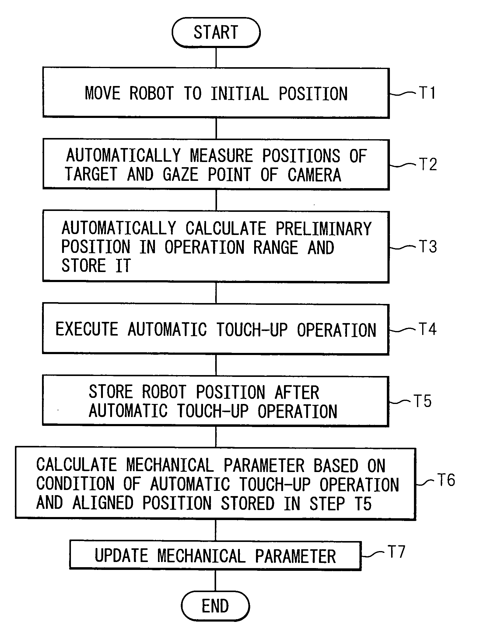
[0034]As described above, in order to calibrate a robot mechanism, a relationship between input and output displacements of the robot must be measured. Generally, the input displacement means a displacement of each axis of the robot, and is detected by an encoder. Ideally, the output displacement is an absolute displacement of a point in a mechanical interface coordinated system of the robot in a stationary coordinate system. However, since a measurement device itself includes an installation error, a measuring object in relation to the output displacement is often a displacement of the point in the mechanical interface coordinate system relative to the stationary coordinate system.

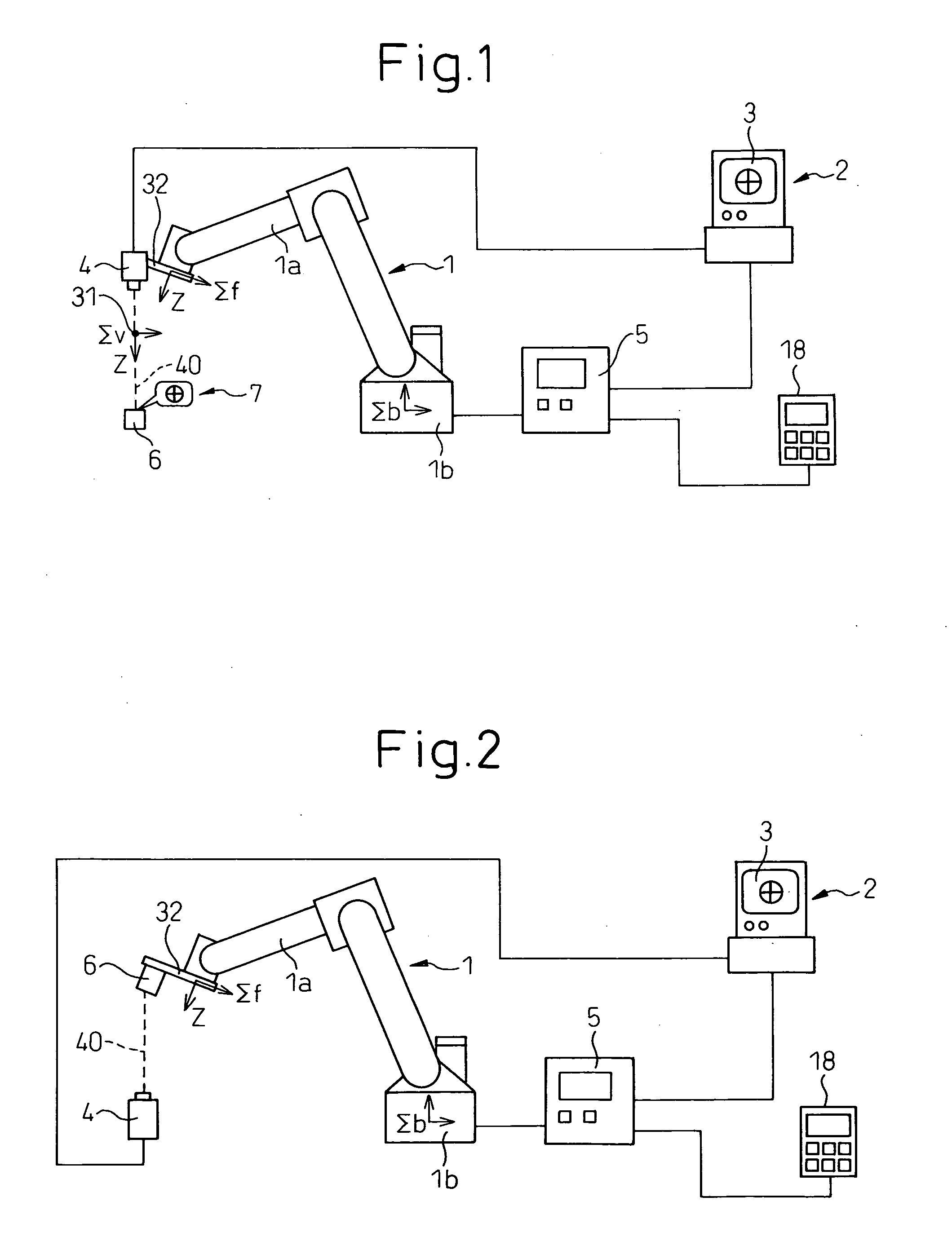
[0035]In the present invention, in order to minimize an error generated by the measurement device, a measurement method is used, in which the position and the orientation angle of the robot are adjusted (or aligned) such that the positional relationship between a fixed point in the mechanical interface co...


PUM


Abstract

A calibration device and method for automatically determining the position and the orientation of a robot used for measurement. First, an initial position of a preliminary position is generated based on a designated basic position, and it is judged whether the initial position is within an operation range of the robot. If the robot cannot reach the initial position, the preliminary position is adjusted close to the basic position. Otherwise, the preliminary position is evaluated by calculating an evaluation index of the preliminary position. When the evaluation index does not satisfy a predetermined condition, an initial value of an posture angle is increased.

Description

RELATED APPLICATIONS[0001]The present application claims priority from Japanese Patent Application No. 2007-25323, filed on Feb. 5, 2007, the entire contents of which are fully incorporated herein by reference.BACKGROUND OF THE INVENTION[0002]1. Field of the Invention[0003]The present invention relates to a calibration device and a calibration method for mechanical parameters of an industrial multi-jointed robot. In particular, the invention relates to a device and a method for automatically generating the position and the orientation a robot used for measuring in calibration.[0004]2. Description of the Related Art[0005]A method for positioning a robot with a high degree of accuracy is known, in which the relationship between inputted and outputted displacements of the robot is measured and the optimum values of the mechanical parameters of the robot is evaluated or corrected based on a measured result. Such a method for correction is generally referred to as “calibration”. As gener...

Claims


Application Information

Patent Timeline
IPC IPC(8): G06F17/00
CPCB25J9/1692G01B11/002G05B2219/39393G05B2219/39045G01B21/042
Inventor BAN, KAZUNORITAKIZAWA, KATSUTOSHISHEN, GANG
Owner FANUC LTD
Why Eureka
Try Eureka