Bi-metal chisel blade

Inactive Publication Date: 2008-08-14
STANLEY WORKS THE
View PDF32 Cites 29 Cited by
  • Summary
  • Abstract
  • Description
  • Claims
  • Application Information

AI Technical Summary

Benefits of technology

[0009]One embodiment comprises a chisel comprising a handle, an elongated working portion, and a shank portion. The elongated working portion and a shank portion are joined with the handle. The elongate working portion has a main body portion and cutting portion. The main body portion is formed from a relatively lower grade steel, and the cutting portion is formed from a relatively higher grade ste

Problems solved by technology

However, in such bi-material blade structures, the connection of the blad

Method used


Image

  • Bi-metal chisel blade
  • Bi-metal chisel blade
  • Bi-metal chisel blade

Examples


Embodiment Construction

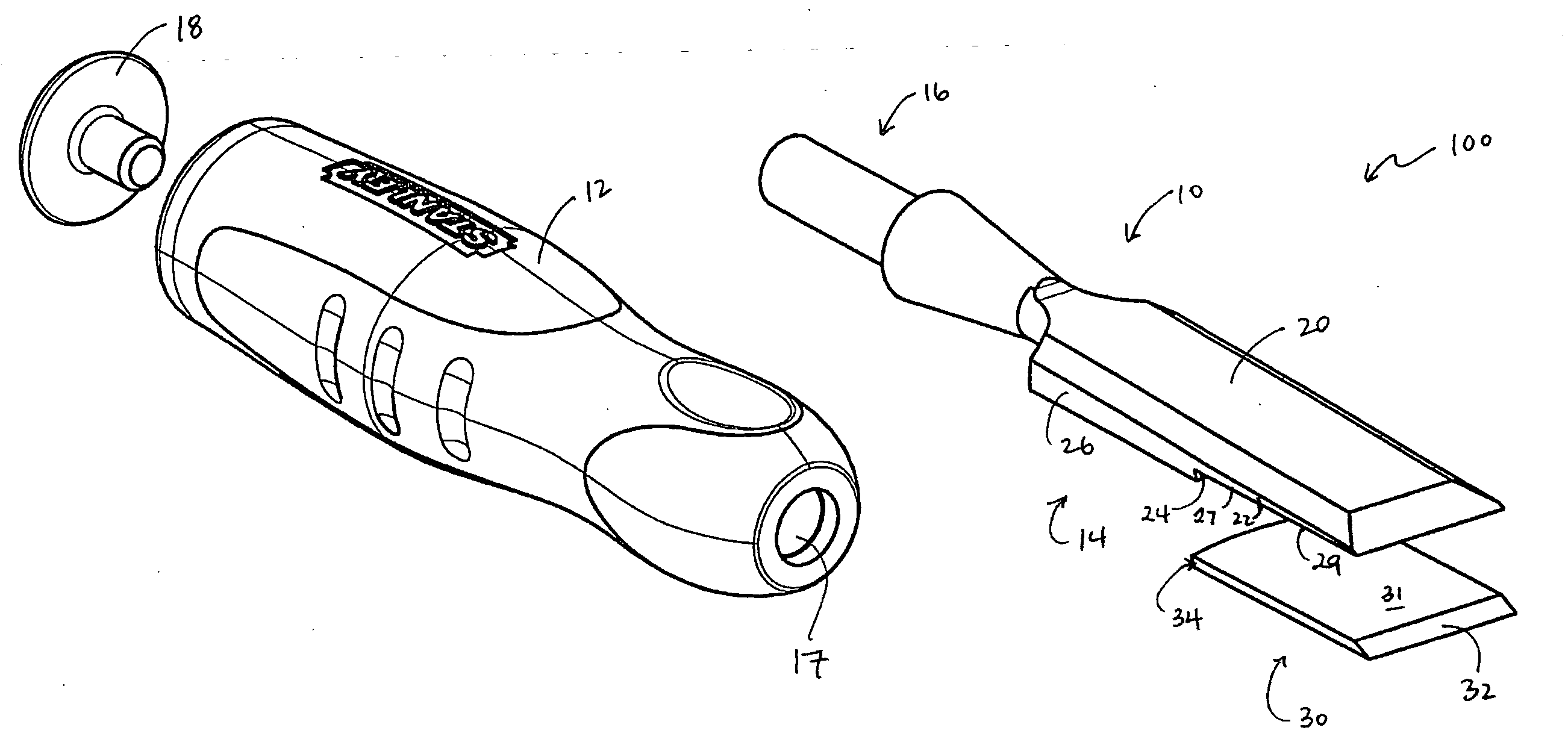
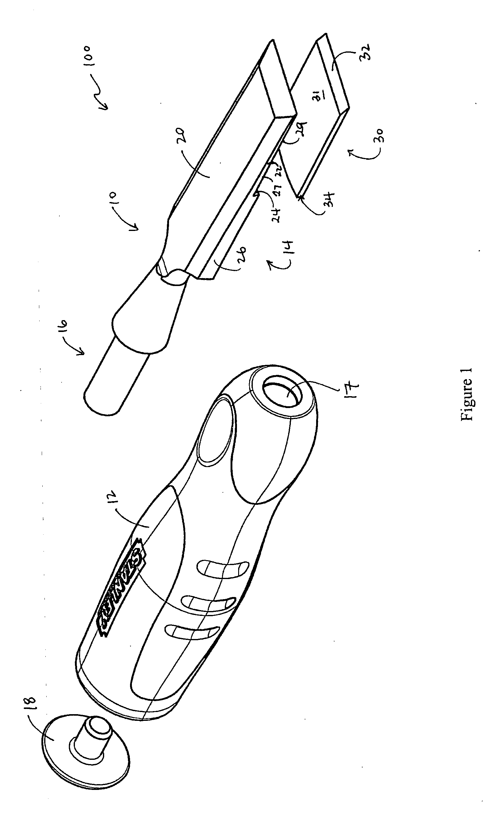
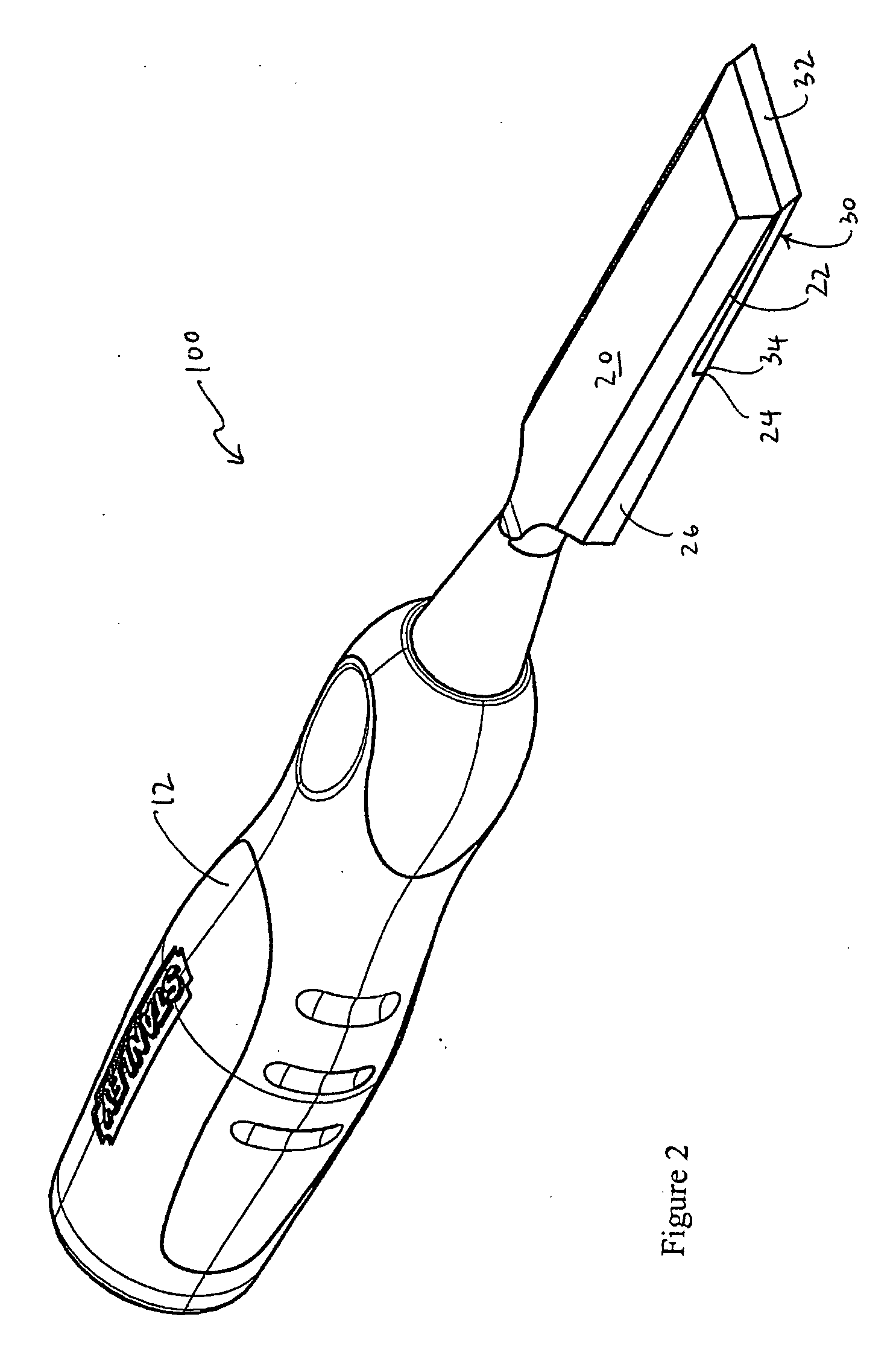
[0026]Referring now more particularly to the drawings, FIG. 1 is an exploded perspective view and FIG. 2 is an assembled perspective view of a chisel 100 in accordance with one embodiment of the invention. The chisel 100 includes a blade 10 and a handle 12 that are connected to one another. Handle 12 comprises an opening 17 for receiving shank portion 16 of chisel blade 10. In an alternate embodiment, handle 12 may be molded around shank portion 16. Handle 12 may also comprise an end cap 18 for striking by another tool, such as a hammer. Handle 12 and end cap 18 are made of materials known to withstand impact. For example, handle 12 may be made of a polymer, and end cap 18 may be made of steel. Handle 12 may be contoured, shock absorbent, ergonomic, or other type of handle known in the art.

[0027]Chisel blade 10 comprises an elongate working portion 14 that is joined with a shank portion 16. The joining of the shank portion 16 and handle 12 form a hand-held chisel 100 that may be use...


PUM

PropertyMeasurementUnit
Thicknessaaaaaaaaaa
Forceaaaaaaaaaa
Hardnessaaaaaaaaaa

Abstract

A chisel with a bi-material blade comprising a main body of low grade steel and a cutting portion of higher grade steel. The cutting portion of higher grade steel provides longer life and decreases the need for frequent sharpening. The main body and cutting portion are connected using an arcuate interface. Additionally, the main body and cutting portion may have a radiussed cross-sectional connection. The arcuate interface and radiussed cross-section help absorb the shear and impact forces applied to the tool.

Description

BACKGROUND OF THE INVENTION[0001]1. Field of Invention[0002]The present invention is generally related to chisels. More particularly, the application relates to chisels having an improved cutting insert.[0003]2. Description of Related Art[0004]Chisels typically include a blade with a sharp cutting edge for carving, shaving, or cutting work pieces. The sharpened edge of the blade becomes dull with continuous use, requiring the craftsman to re-sharpen and re-hone the blade edge regularly in order to produce a satisfactory and predictable performance.[0005]Prior art has attempted to alleviate the craftsman's need to sharpen the blade by providing a replaceable chisel blade. These blades are removable from the tool shank and allow the craftsman to replace the blade when needed.[0006]Other chisels attempt to lengthen the life of the blade by constructing a blade of relatively harder metallic material. Specifically, it is known to provide a chisel blade made of two different steel materia...

Claims


Application Information

Patent Timeline
IPC IPC(8): B25D3/00B23P11/00
CPCB25D3/00B25D2222/42B25D2250/071Y10T29/49826B25D2250/111B25D2250/275B25D2250/075
Inventor KASPER, SCOTT
Owner STANLEY WORKS THE
Why Eureka
Try Eureka