

Fluorescent Lamp
a fluorescent lamp and fluorescent technology, applied in the field of fluorescent lamps, can solve the problems of high power consumption and achieve the effect of excellent luminous efficiency and free from non-uniform luminan
- Summary
- Abstract
- Description
- Claims
- Application Information
AI Technical Summary
Benefits of technology
Problems solved by technology
Method used
Image

Examples
example 1
[0021]A fluorescent material having a particle size of 1 μm and prepared by a pulverizing method was supplied into a butyl acetate solvent obtained by dissolving nitrocellulose and increased in viscosity, dispersed by agitation, and left for 10 minutes. Then, it was confirmed that the fluorescent material did not precipitate at the bottom of the solvent. As a comparative example, a typical fluorescent material was dispersed in a similar solvent. In this case, it was confirmed that the fluorescent material precipitated after lapse of one minute.
[0022]As the fluorescent material, use may be made of a typical fluorescent material such as a barium / magnesium / aluminum salt doped with europium. The fluorescent material is generally classified into a long-wavelength excitation type (red) material, a medium-wavelength excitation type (green) material, and a short-wavelength excitation type (blue) material. For example, a white lamp emits white light by mixing the three types of materials in ...
example 2
[0024]The dispersion liquid prepared in Example 1 was applied by dip coating onto a borosilicate glass plate of 40 mm square and 1 mm thick in a state where one surface of the plate was covered with a mask. After removing the mask, the dispersion liquid was sintered at 400° C. to form a fluorescent layer having a thickness of 2 μm (fluorescent-material-applied glass A). Ultraviolet ray of 254 nm was irradiated to the plate on the side coated with the fluorescent layer. The luminance of the uncoated side was measured.
[0025]Similarly, a sample with a fluorescent layer having a thickness of 10 μm was prepared by the use of the same dispersion liquid (fluorescent-material-applied glass B) and another sample with the fluorescent layer having a thickness of 10 μm and a particle size of 3 μm was prepared (fluorescent-material-applied glass C). Then, the luminance was measured.
[0026]As a result of measurement, it was confirmed that the fluorescent-material-applied glass A had the luminance ...
example 3
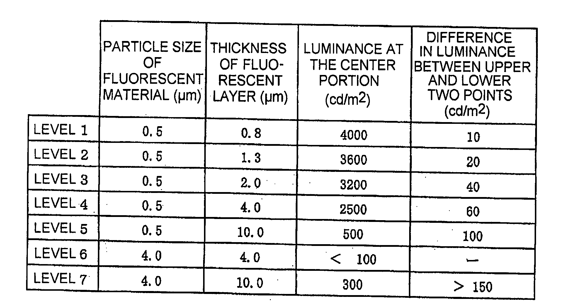
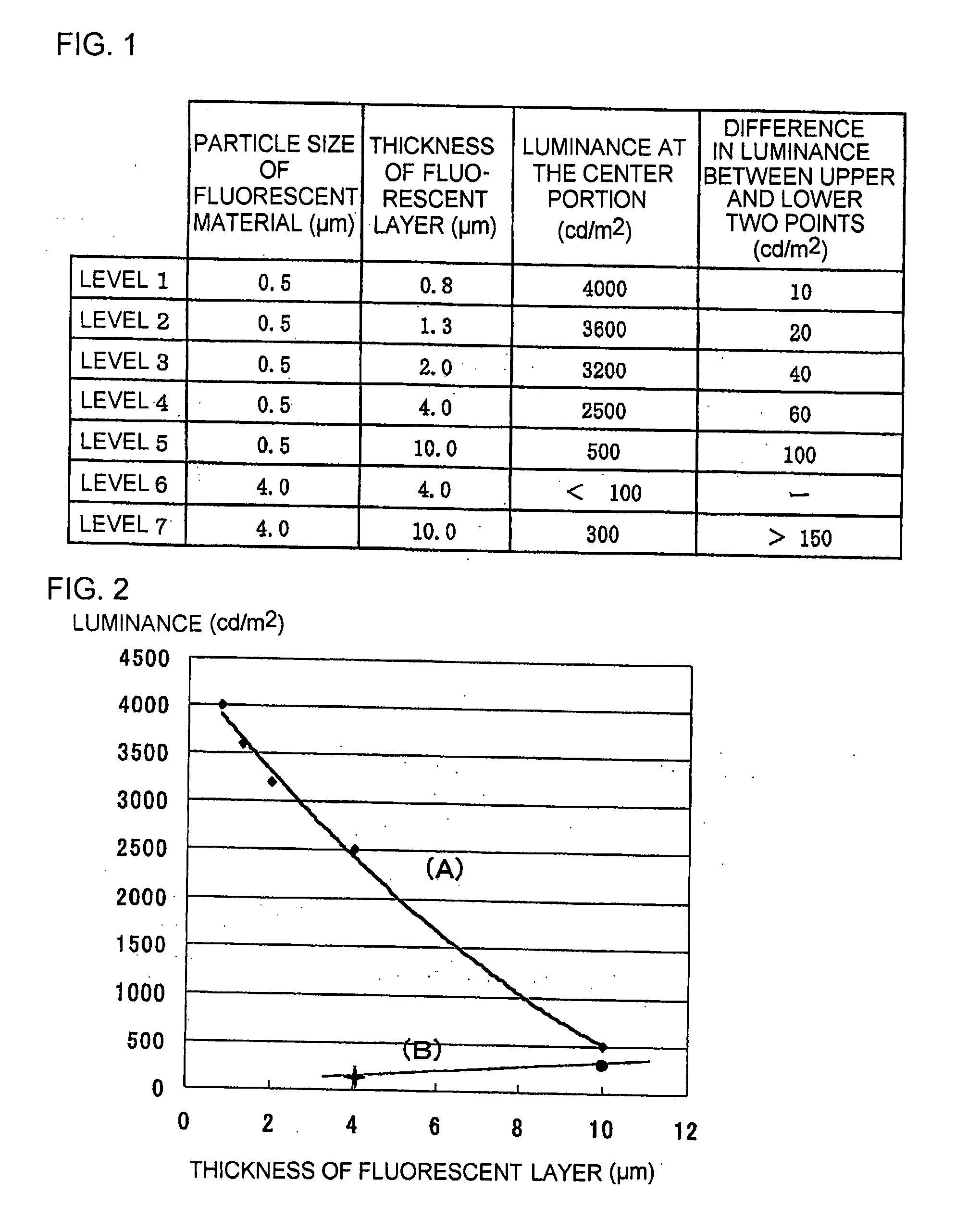
[0028]As an example 3, in the manner similar to the example 2, fluorescent materials of different particle sizes were applied by dip coating to different thicknesses onto a borosilicate glass plate of 40 mm square and 1 mm thick in a state where one surface of the plate was covered with a mask. After removing the mask, sintering at 400° C. was carried out. Thus, various kinds of fluorescent layers having different particle sizes and different thicknesses were formed. Ultraviolet ray of 254 nm was irradiated to the side coated with each of the various kinds of the fluorescent layers. The luminance of the uncoated side was measured. The levels and the result of measurement are shown in FIGS. 1 and 2.
[0029]The luminance with the fluorescent material of a particle size of 0.5 μm is depicted by a line (A) in FIG. 2. The luminance with the fluorescent material of a particle size of 4 μm is depicted by a line (B) in FIG. 2. The luminance with the fluorescent material having a particle size...
PUM
 Abstract
Description
Claims
Application Information