Wireless communication apparatus
a wireless communication and wireless communication technology, applied in multiplex communication, orthogonal multiplex, baseband system details, etc., can solve problems such as difficulty in performing automatic gain control (agc)
- Summary
- Abstract
- Description
- Claims
- Application Information
AI Technical Summary
Benefits of technology
Problems solved by technology
Method used
Image
Examples
first embodiment
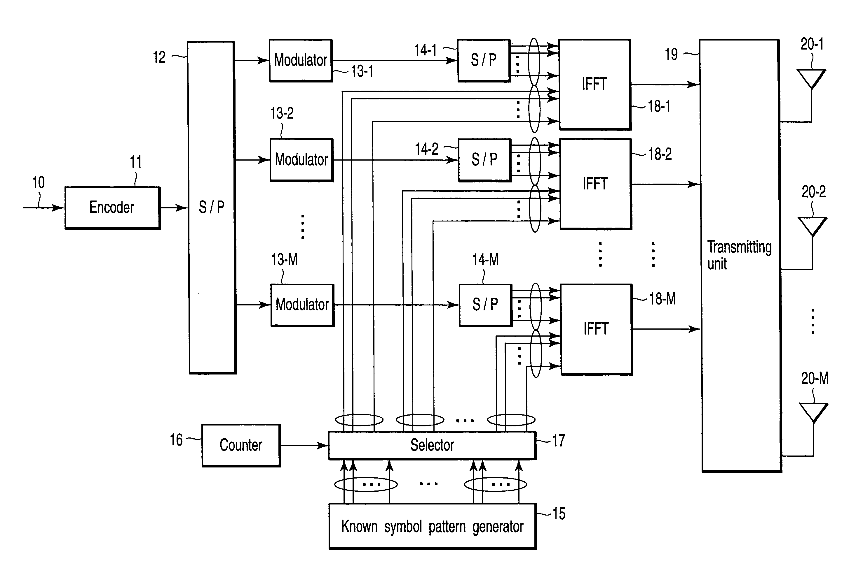
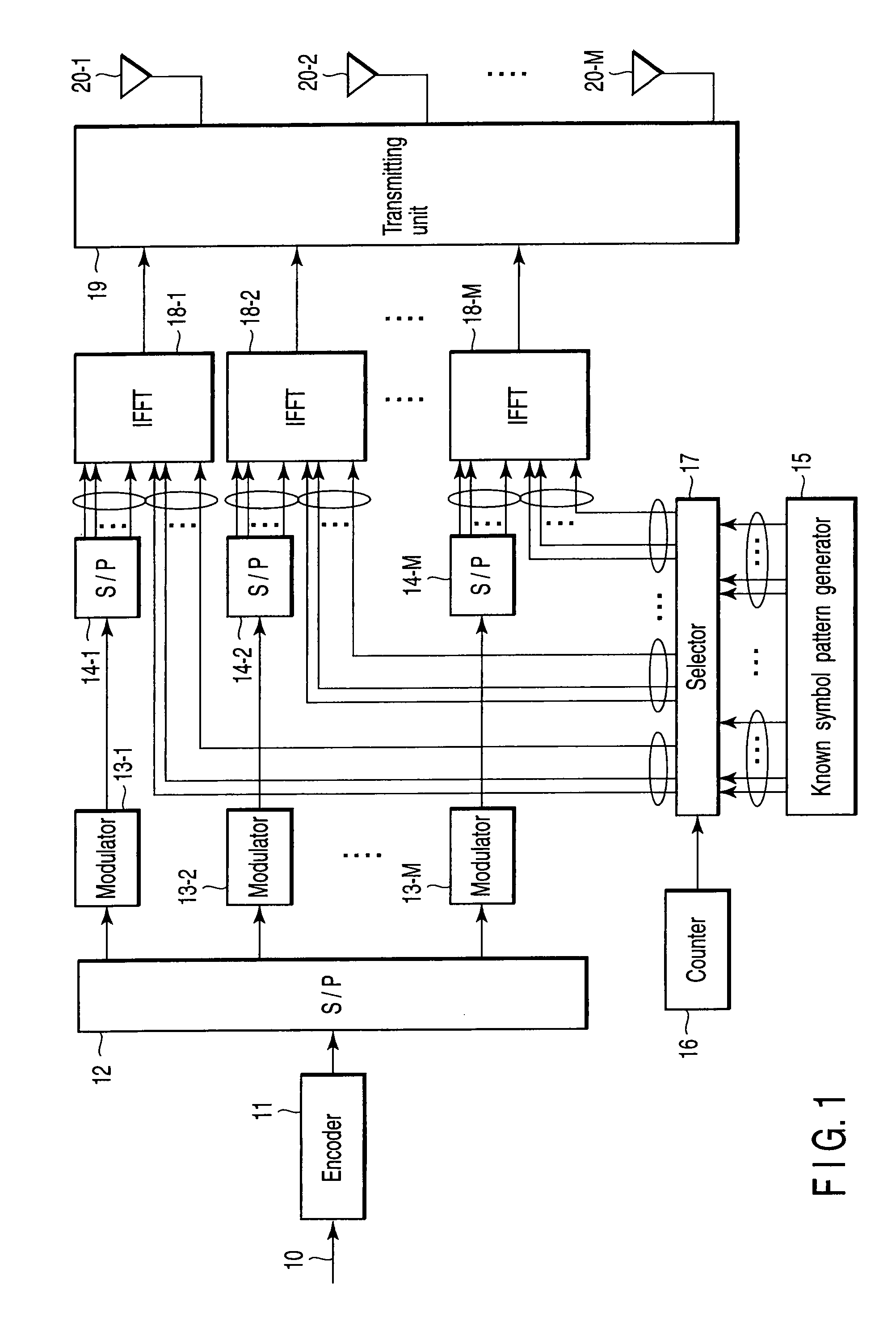
[0032]First, a transmitter according to a first embodiment of the present invention will be described below with reference to FIG. 1. FIG. 1 shows physical layers of this transmitter. Data (a bit stream) 10 is transmitted in certain transmission units (e.g., frames or packets) from an upper layer. An encoder 11 performs, e.g., error correction coding on the input data 10, and generates a coded bit sequence. A serial-to-parallel (S / P) converter 12 divides the coded bit sequence into a plurality of streams by serial-to-parallel conversion. Modulators 13-1 to 13-M map these streams on a complex plane to generate modulated data symbols.
[0033]S / P converters 14-1 to 14-M perform serial-to-parallel conversion on the modulated data symbols so that they are transmitted on subcarriers of orthogonal frequency-division multiplexing (OFDM). In addition, inverse fast Fourier transform (IFFT) units 18-1 to 18-M transform these signals on the frequency domain into the time domain signals. The outpu...
second embodiment
[0082]In the first embodiment, the number N of subcarriers is divisible by the number M of antennas. In a second embodiment, an example of a case in which N is indivisible by M, such as a long preamble of a wireless LAN, will be explained. Of 64 IFFT samples in a wireless LAN, usable subcarriers are 52 subcarriers, and other subcarriers are not carried on signals. In this case, if the number M of antennas is three, N is indivisible by M, so the number of subcarriers allocated to each antenna changes from one antenna to another.
[0083]For example, in a long preamble L−26,26 of the IEEE 802.11a, signals having patterns as shown in Table 2 below are present in the −26th to 26th subcarriers, and transmitted by BPSK modulation.
TABLE 2IEEE 802.11a long preamble structure (L−26, 26)Carrier number−26−25−24−23−22−21−20−19−18−17−16−15−14Sequence11−1−111−11−11111Carrier number−13−12−11−10−9−8−7−6−5−4−3−2−1Sequence11−1−111−11−11111Carrier number+1+2+3+4+5+6+7+8+9+10+11+12+13Sequence1−1−111−11−11...
third embodiment
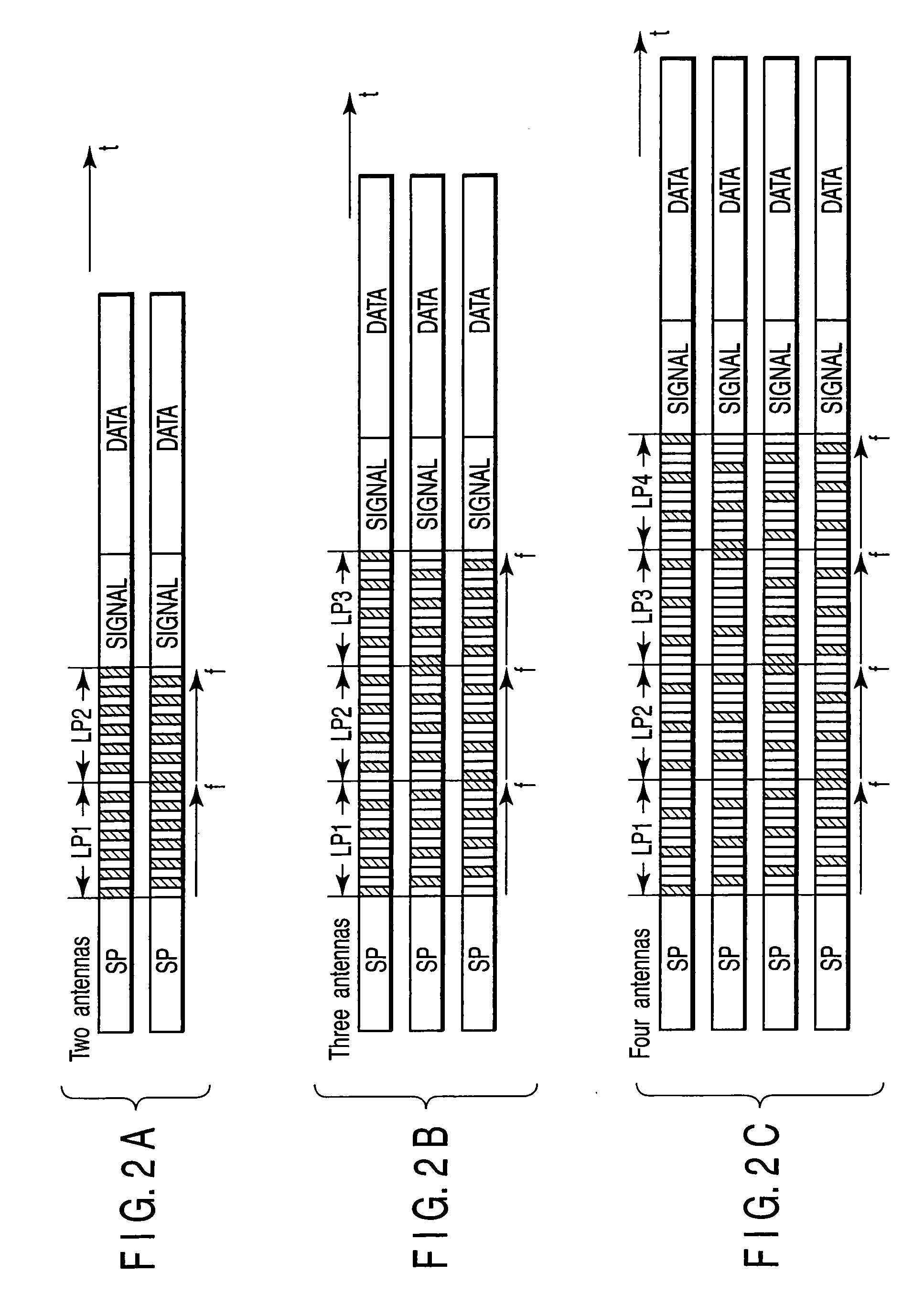
[0097]A method of transmitting known symbols for channel estimation according to a third embodiment of the present invention will be described below with reference to FIGS. 4A and 4B. FIGS. 4A and 4B show the structures of radio frames containing preambles when the numbers of antennas which simultaneously transmit known symbols are two and three, respectively.
[0098]In the first embodiment, channel estimation can be performed by receiving M known symbols for the number M of transmitting antennas. In contrast, the third embodiment assumes the reception of 2M known symbols in order to raise the accuracy of channel estimation in FIG. 3. When the known symbol pattern LP(M,n) (M is the number of transmitting antennas, and n is the pattern number) explained in the first embodiment is used, known symbols are transmitted as follows in the third embodiment.
[0099]Antenna 1: transmitted in the order of LP(2,1), LP(2,1), LP(2,2), and LP(2,2);
[0100]Antenna 2: transmitted in the order of LP(2,2), ...
PUM
 Abstract
Description
Claims
Application Information
 - R&D
- Intellectual Property
- Life Sciences
- Materials
- Tech Scout
- Unparalleled Data Quality
- Higher Quality Content
- 60% Fewer Hallucinations
Browse by: Latest US Patents, China's latest patents, Technical Efficacy Thesaurus, Application Domain, Technology Topic, Popular Technical Reports.
© 2025 PatSnap. All rights reserved.Legal|Privacy policy|Modern Slavery Act Transparency Statement|Sitemap|About US| Contact US: help@patsnap.com


