
Wireless receiver apparatus

a receiver and wireless technology, applied in the direction of digital transmission, gain control, transmission, etc., can solve the problems of degrading an error rate characteristic and deteriorating errors rate characteristics, so as to improve the data error rate characteristic, suppress the distortion of the received signal, and improve the accuracy of the channel estimation

Inactive Publication Date: 2009-11-10
FUJITSU LTD
View PDF10 Cites 5 Cited by
  • Summary
  • Abstract
  • Description
  • Claims
  • Application Information

AI Technical Summary

Benefits of technology

[0020]An object of the present invention is to provide a wireless receiver apparatus capable of carrying out channel compensation without deteriorating a data error rate as much as possible even when AGC gains fluctuate.
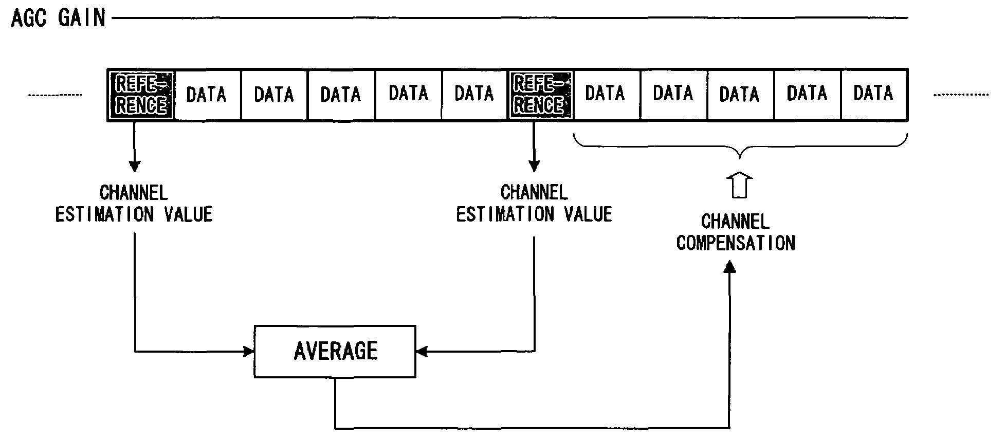
[0022]A consideration of an updating timing of an AGC gain and of an AGC gain difference between the pre- and post-updates makes it possible to suppress a distortion of a received signal due to a difference of AGC gains, thereby enabling a highly accurate channel estimation, resulting in improving a data error rate characteristic.

Problems solved by technology

The above described results in the problem of an error rate characteristic being deteriorated if AGC gains are different between a data symbol to be demodulated and a reference symbol for calculating a channel estimation value.
And if AGC gains are different among a plurality of reference symbols for performing channel estimations, a channel estimation value is added by an amplitude fluctuation effect due to the difference of the AGC gains, thereby resulting in the problem of degrading an error rate characteristic if a channel compensation is carried out by averaging or linearly interpolating the channel estimation value as is.

Method used


Image

  • Wireless receiver apparatus
  • Wireless receiver apparatus
  • Wireless receiver apparatus

Examples


Embodiment Construction

[0043]A preferred embodiment of the present invention is configured to enable a highly accurate data demodulation by avoiding a distortion of a received signal due to a difference in AGC gains.

[0044]A wireless receiver apparatus according to the embodiment of the present invention is configured to change over calculation methods of a transmission estimation value depending on a presence or absence of a change in AGC gain. The apparatus comprehends a timing at which an AGC gain is updated and the pre- and post-updated AGC gain values, making it possible to determine a frame for a reference, calculate an AGC gain difference relative to the frame and calculate a channel estimation value based on these pieces of information, thereby being capable of carrying out a highly accurate data demodulation.

[0045]Particularly, in the case of the AGC gains being changed, what is conceivable is to carry out a channel compensation by using a channel compensation coefficient which is obtained by usin...


PUM


Abstract

When carrying out a channel compensation of a data symbol, a channel estimation value of the reference symbol of the frame itself and that of a reference symbol of the preceding frame are used. In this event, if an AGC gain at the time of a channel estimation value by a reference symbol of the frame itself is different from that of a frame of the reference symbol of the preceding frame, and if an AGC gain of the reference symbol of the frame itself is the same as that of a data symbol to be subjected to a transmission compensation, then the channel estimation value by the reference symbol of the preceding frame is corrected so as to cancel the difference of the AGC gains, followed by using it for a channel compensation of the data symbol.

Description

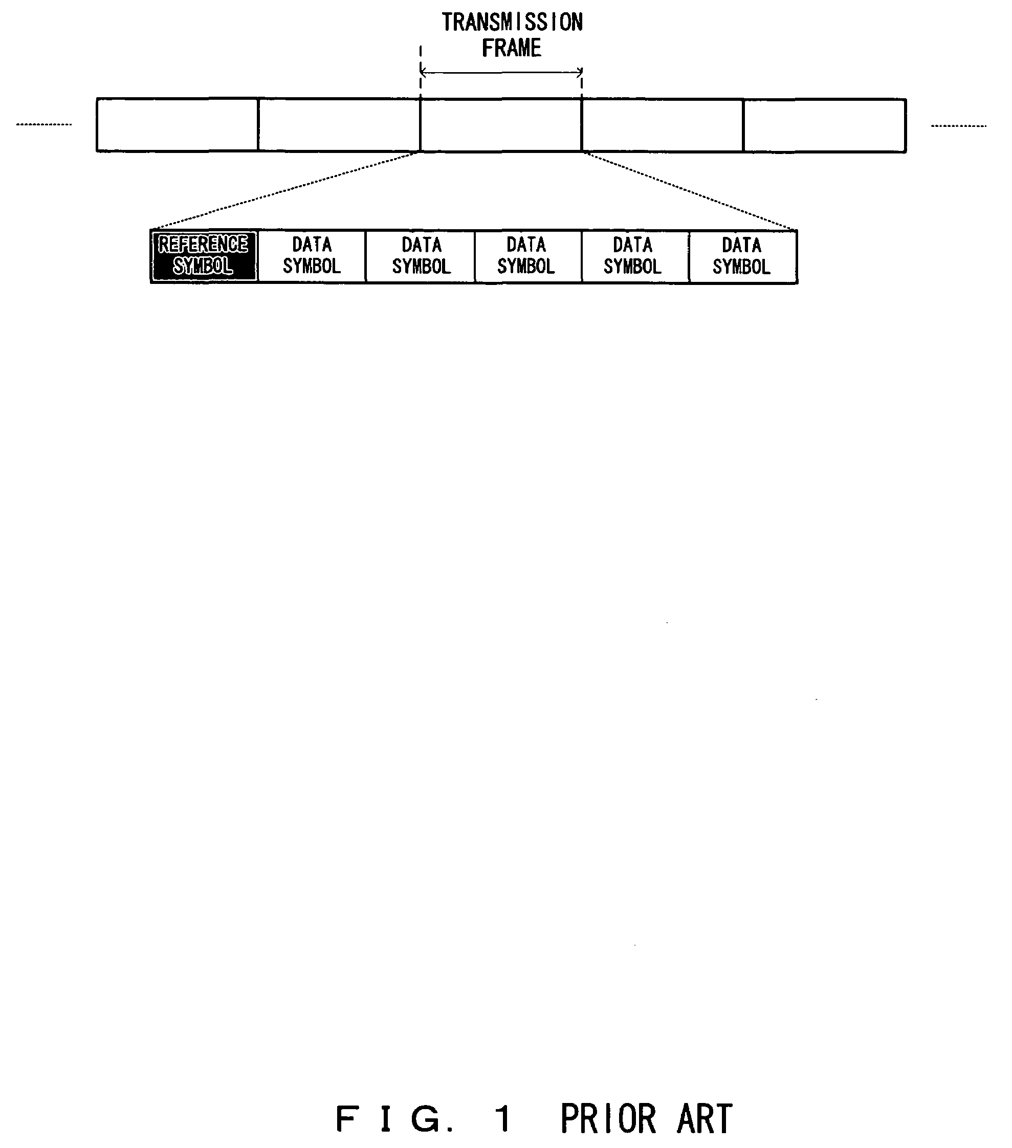
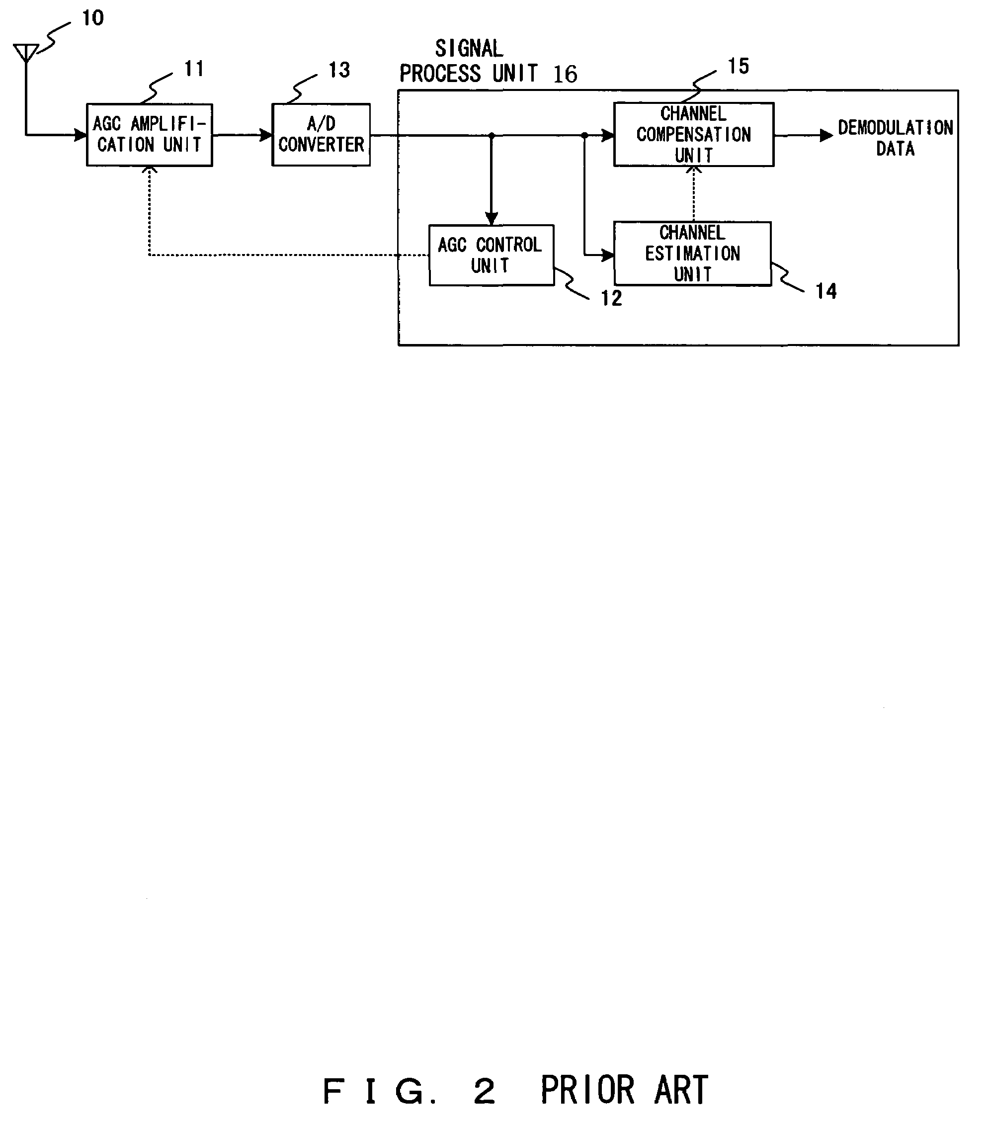
BACKGROUND OF THE INVENTION[0001]1. Field of the Invention[0002]The present invention relates to a wireless receiver apparatus comprising an automatic gain control function.[0003]2. Description of the Related Art[0004]FIG. 1 exemplifies a frame format used for a wireless telecommunication transmission system.[0005]Referring to FIG. 1, one frame is comprised by one reference symbol and five data symbols, with the reference symbol being time-multiplexed in relation to the data symbols at a constant interval. Note that there is no need of five data symbols existing relating to one reference symbol, and other comprisals are also the same. The term “reference symbol” corresponds to “pilot symbol” in the W-CDMA system, whereas the present specification uses the term “reference symbol” in order to discuss more generally.[0006]A wireless receiver apparatus performs a channel estimation and demodulates a data symbol by compensating for a channel response. A channel estimation circuit calcula...

Claims


Application Information

Patent Timeline
Patent Type & Authority Patents(United States)
IPC IPC(8): H04L27/08H04B1/06
CPCH04L25/0228H04L25/0232H03G3/20
Inventor SATO, TADAHIRO
Owner FUJITSU LTD
Learn More