
Touch determination with interaction compensation

a compensation and interaction technology, applied in the field of touch sensing systems, can solve the problems of reducing the transmitted light, affecting the image, and affecting the accuracy of the image, so as to facilitate or enable such triangulation, suppress image distortion, and fast and well-controlled compensation

Inactive Publication Date: 2014-11-27
FLATFROG LAB
View PDF3 Cites 33 Cited by
  • Summary
  • Abstract
  • Description
  • Claims
  • Application Information

AI Technical Summary

Benefits of technology

The patent text describes a method for improving touch detection in an optical touch system by compensating signal values to reduce distortions caused by interaction imbalance. The compensated signal values are then used to generate touch data, which includes location coordinates, shape, area, and size of the objects. This approach allows for a faster and better-controlled compensation and can also be combined with existing techniques for image generation. The technical effects of the patent include improved accuracy and responsiveness of touch detection.

Problems solved by technology

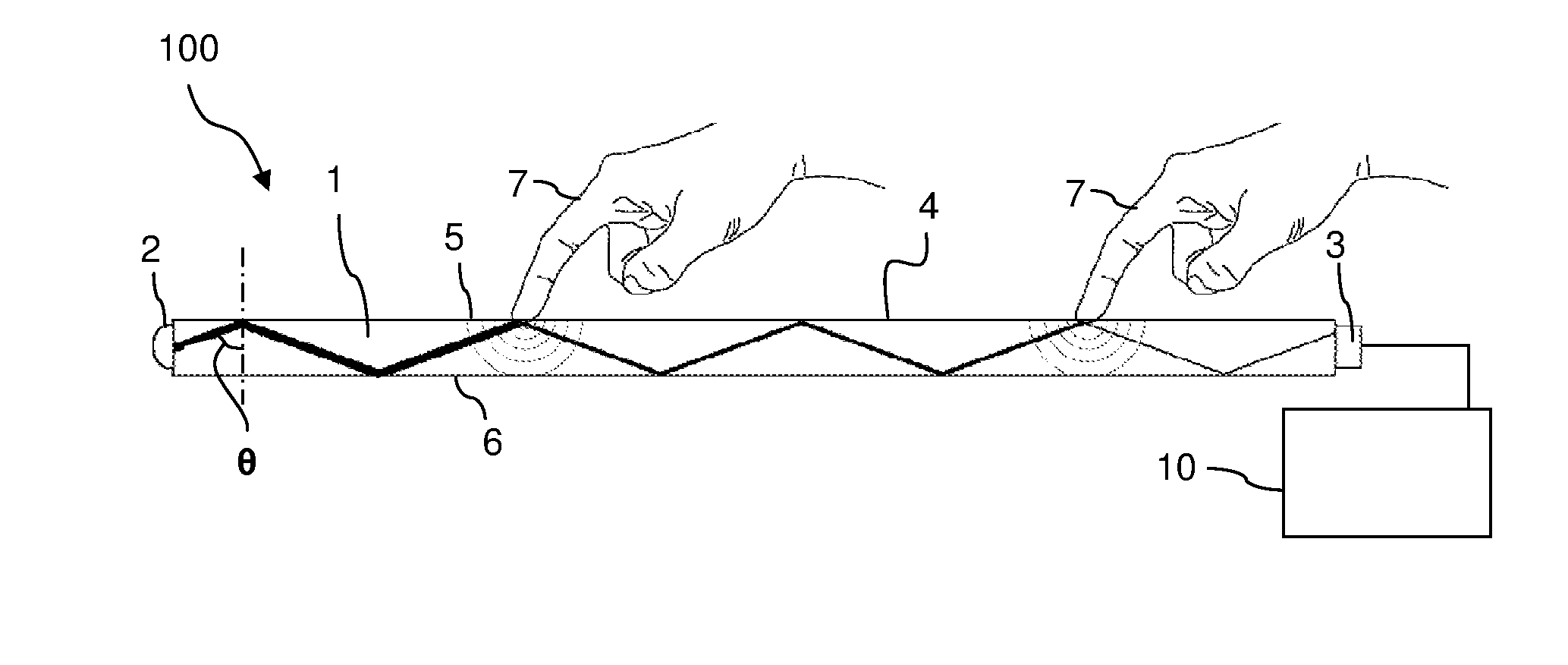
An object touching the panel may frustrate the light whereby part of the light will leave its original propagation path and the detected signal will decrease.
An object touching the panel frustrates the light inside the panel and thereby decreases the transmitted light.
Such an interaction imbalance may cause inaccuracies in the generated touch data, or even make it difficult to generate the touch data.
The interaction imbalance occurs for all detection lines that interact with the object.

Method used


Image

  • Touch determination with interaction compensation
  • Touch determination with interaction compensation
  • Touch determination with interaction compensation

Examples


first embodiment

[0081]In a first embodiment, the input values st are compensated for the above-mentioned line imbalance, including the attenuation imbalance caused by the different lengths of the detection lines. As explained in Section 2, the input values st are derived from the projection signals It in a format matched to the reconstruction function ′, e.g. to represent attenuation or transmission.

[0082]FIG. 12 is a flowchart of a compensation method according to the first embodiment. The method operates in a repeating sequence of steps 50-56, wherein each sequence of steps is denoted an “iteration” or a “frame”. The method starts with a step 50 of obtaining a current projection value for each detection line. In some touch systems, this may not result in a projection value for every detection line in the system, but rather a projection value for each detection line deemed relevant in a particular frame. The current projection values It may be pre-processed, e.g. for noise reduction or ambient / con...

second embodiment

[0100]FIG. 15 is a flowchart of a compensation method according to a Here, preliminary locations of objects deemed to exist on the touch surface in the current frame are identified and used for obtaining the compensation data. In a first variant, the preliminary locations may be used for identifying the detection lines that are affected by the touching objects. This may be used to selectively operate the compensation values only on the affected detection lines, e.g. if needed to avoid that unaffected detection lines otherwise are compensated for an attenuation imbalance that does not exist. In a second variant, the preliminary locations may be used for obtaining compensation data that compensates for variations in the relevant power profile along the detection line, e.g. to account for effects of light scattering in the FTIR system.

[0101]Steps 50, 54 and 56 are identical to the first embodiment. After step 50, step 51A processes the projection values to generate a preliminary atten...


PUM


Abstract

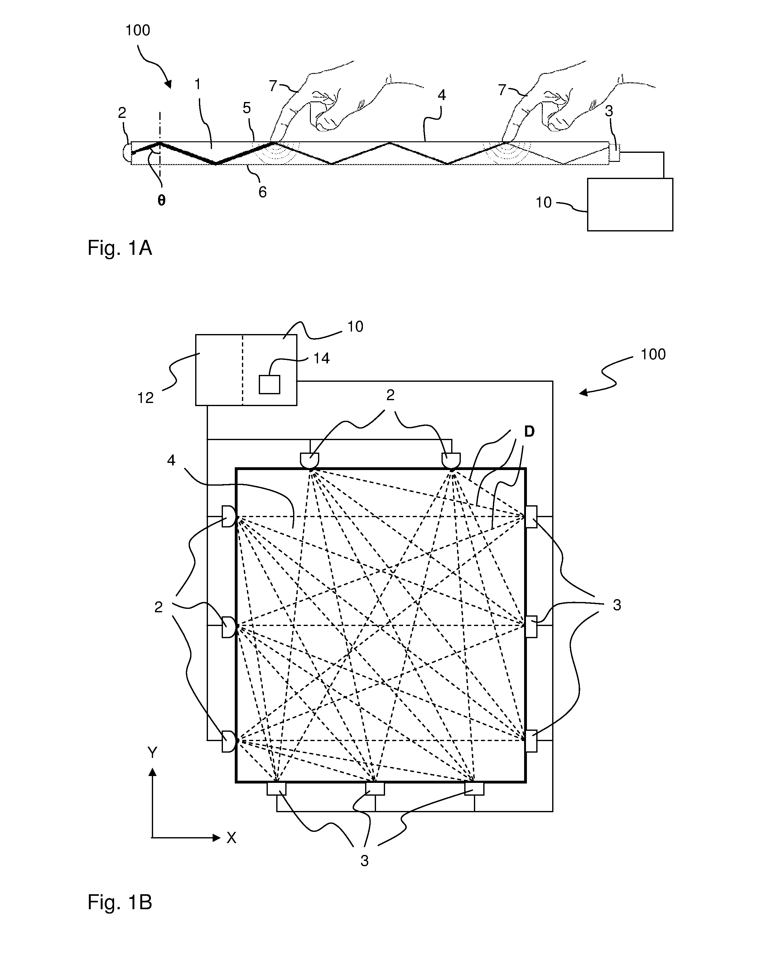
A device implements a data processing method for an optical FTIR-based touch system. The touch system defines detection lines across a surface portion of a panel by propagating light inside the panel from a plurality of incoupling points to a plurality of outcoupling points, such that each location on the surface portion is illuminated by incident light rays. At least one light detector is coupled to the outcoupling points to generate an output signal. The device obtains signal values for the detection lines from the output signal and processes the signal values to at least partly compensate for variations in the apparent interaction among the subset of detection lines that interact with an object on the surface portion.

Description

CROSS-REFERENCE TO RELATED APPLICATIONS[0001]The present application claims the benefit of Swedish patent application No. 1151261-3, filed 22 Dec. 2011, and U.S. provisional application No. 61 / 579,291, filed 22 Dec. 2011, both of which are incorporated herein by reference.TECHNICAL FIELD[0002]The present invention relates to touch sensing systems that operate by light transmission inside light transmissive panels, and in particular to the processing of touch signals in such systems.BACKGROUND ART[0003]Touch sensing systems (“touch systems”) are in widespread use in a variety of applications. Typically, the touch systems are actuated by a touch object such as a finger or stylus, either in direct contact, or through proximity (i.e. without contact), with a touch surface. Touch systems are for example used as touch pads of laptop computers, in control panels, and as overlays to displays on e.g. hand held devices, such as mobile telephones. A touch panel that is overlaid on or integrate...

Claims


Application Information

Patent Timeline
Patent Type & Authority Applications(United States)
IPC IPC(8): G06F3/042G06F3/041
CPCG06F3/0421G06F2203/04109G06F3/0412G06F3/0418
Inventor WALLANDER, MATS PETTERJUHLIN, PETERKRUS, MATTIAS
Owner FLATFROG LAB
Learn More