
Image processing apparatus and method of controlling the same

a technology of image processing and display device, which is applied in the direction of selective content distribution, television systems, instruments, etc., can solve the problems of distortion of display image in actual pursuit and the inability to make full use of the dynamic range of display devices, and achieve the effect of light processing load

Inactive Publication Date: 2009-02-12
CANON KK
View PDF19 Cites 33 Cited by
  • Summary
  • Abstract
  • Description
  • Claims
  • Application Information

AI Technical Summary

Benefits of technology

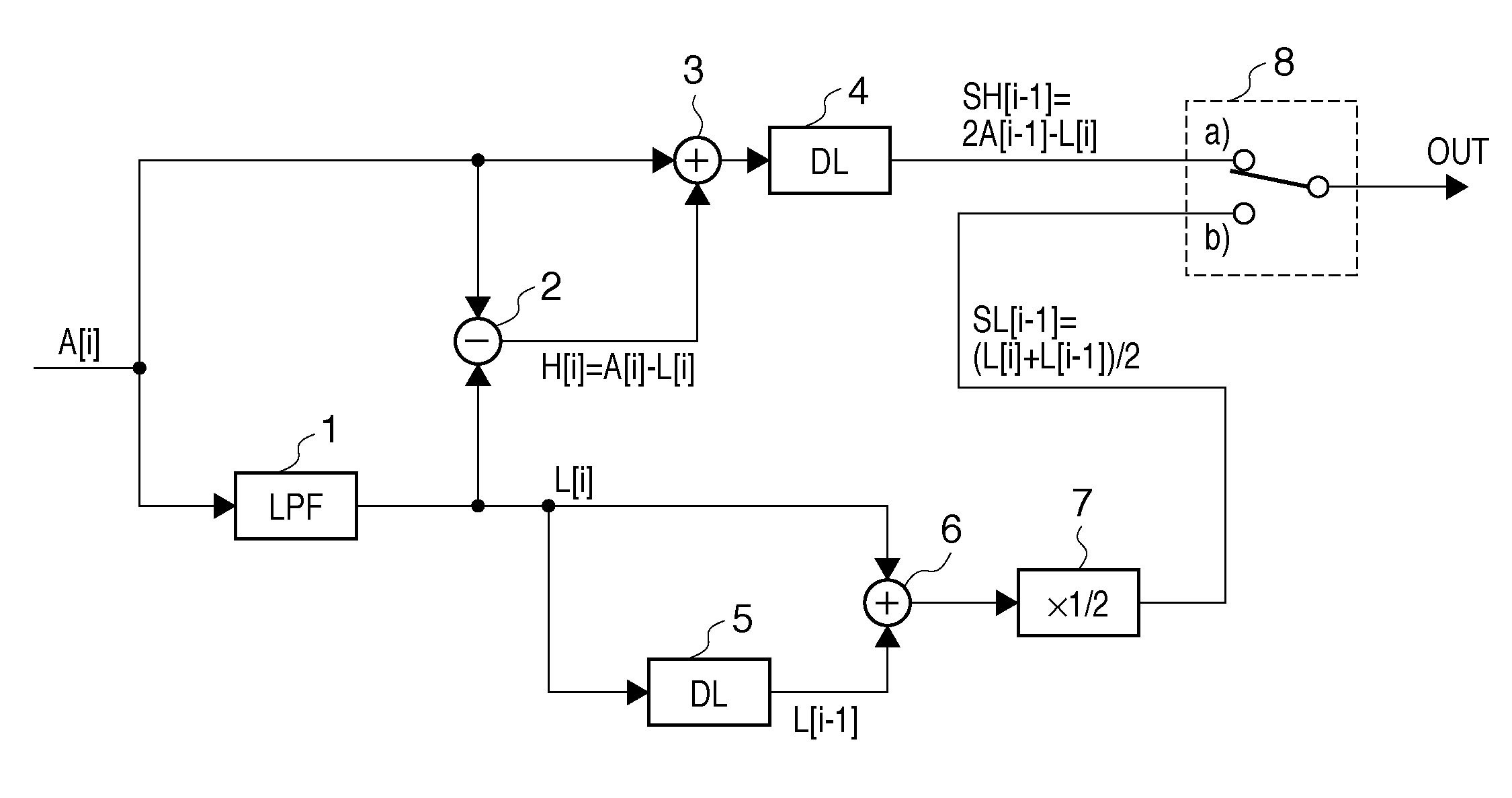
The present invention aims to improve the display of moving images by addressing two problems: distortion and limited dynamic range. The first problem is caused by the separation of high-frequency and low-frequency components of an image, which leads to ghosting or tail-blurring when the display level of one sub-frame is moved to the other. The second problem is that the maximum display intensity of one sub-frame is limited when the display level of another sub-frame is increased or decreased. The invention proposes a technique to mitigate these problems by separating image data into high-frequency and low-frequency components, storing them, and adding or averaging them to create a new image that has reduced distortion and maximizes the dynamic range of the display.

Problems solved by technology

In examining the “method of separating an image into spatial frequencies and distributing them to sub-frames for display”, two problems are posed.
The first problem is that a display image in actual pursuit has distortion.
The second problem is that it is impossible to make full use of the dynamic range of a display device.
The first problem is supposed to be caused when a spatial high-frequency component and a spatial low-frequency component generated from each frame of an input image are distributed to sub-frames, and the temporal centers of gravity of their components shift in display.

Method used


Image

  • Image processing apparatus and method of controlling the same
  • Image processing apparatus and method of controlling the same
  • Image processing apparatus and method of controlling the same

Examples


first embodiment

Modification of First Embodiment

[0190]An example will be described in which a process equivalent to the first embodiment is implemented by a computer program. An apparatus for executing the computer program can be an information processing apparatus such as a personal computer (PC). The structure and features of the hardware comprising a PC are well known, so will not be described here. We assume that a moving image data file containing m frames per unit time is already stored in a storage device (or storage medium) such as a hard disk. An example will be described in which the CPU executing the application (computer program) of this modification converts the file into moving image data to be played back at twice the frame rate, that is, 2m frames per unit time, and saves the conversion result in the hard disk as a file. The conversion target moving image data is stored in the storage device. The moving image data after double-rate conversion is also stored in the storage device. He...

second embodiment

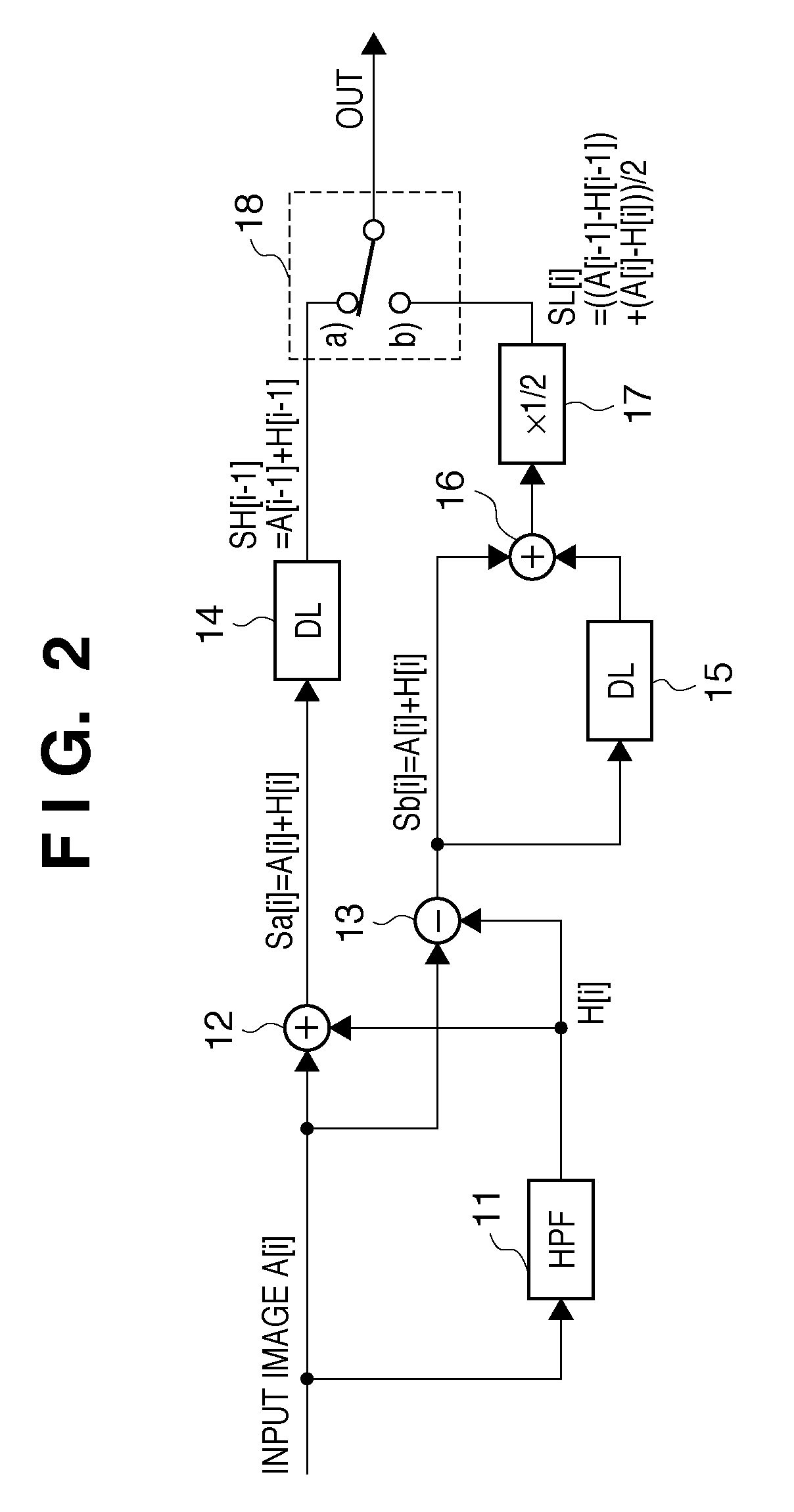
[0207]In the second embodiment, an example of a solution to the above-described second problem will be described. FIG. 17 is a block diagram showing an arrangement of an image processing apparatus according to the second embodiment. The same reference numerals as in FIG. 1 denote the same components in FIG. 17, and a description thereof will be omitted.

[0208]The second problem occurs when each frame of an input image is filtered to separate a spatial high-frequency component related to motion blur and a spatial low-frequency component related to flicker. That is, in a method of displaying an image by concentrating the spatial high-frequency component to one sub-frame and distributing the spatial low-frequency component to both sub-frames, it is impossible to make full use of the dynamic range of the display device.

[0209]“One sub-frame” indicates one of two double-rate frames corresponding to the input image frame. “Both frames” indicates both of the two double-rate frames correspond...

third embodiment

[0278]In the third embodiment, a solution to the above-described second problem will be described.

[0279]In the above-described second embodiment, the distance constant value d of the LPF is appropriately controlled to suppress the ratio of the high-frequency component from becoming excessively high. That is, this prevents the brightness level of display from being saturated (i.e., SH[i]>100%, or SH[i]<0 mathematically).

[0280]The third embodiment proposes a method of preventing a problem even when saturation of the display brightness level (i.e., SH[i]≧100%, or SH[i]<0 mathematically) still occurs after the above-described process. That is, SH[i] and SL[i] which are calculated once are corrected again to prevent any problem.

[0281]FIGS. 21 and 22 show a case in which the method of the embodiment is applied to the prior art in FIG. 6.

[0282]In the prior art shown in FIG. 6, SH[i] and SL[i] can be expressed by

L[i]=LPF(A[i])

H[i]=A[i]−L[i]

SH[i]=L[i]+2H[i]

SL[i]=L[i]

[0283]In the third embodi...


PUM


Abstract

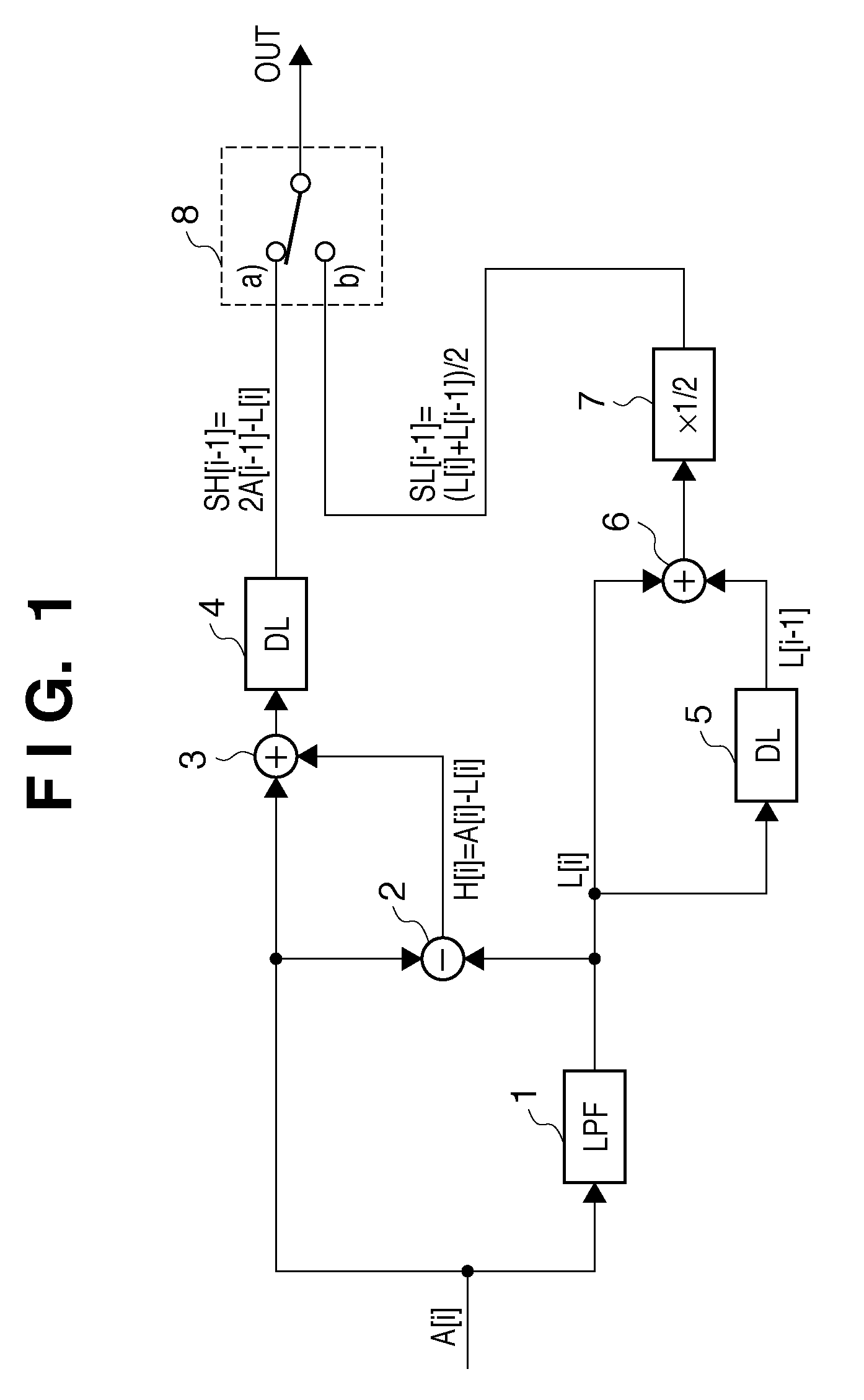
This invention enables, for example, reduction of motion blur in a hold-type display device and reduce flicker in an impulse-type display device by a simple process. For this purpose, an LPF filters a frame of input image data (A[i]) to generate low-frequency image data (L). A subtractor and an adder generate high-frequency image data (SH). Another adder adds the low-frequency image data (L) from a delay circuit to subsequent low-frequency image data. A divider halves the sum to generate low-frequency averaged image data (SL). A switch alternately outputs the high-frequency image data (SH) and the low-frequency image data (SL) every time a frame of image data is input. As a result, the apparatus of this invention can generate output image data having a frame rate twice that of the input image data.

Description

BACKGROUND OF THE INVENTION[0001]1. Field of the Invention[0002]The present invention relates to an image processing apparatus for converting moving image data having a first frame rate into moving image data having a higher frame rate, and a method of controlling the same.[0003]2. Description of the Related Art[0004]Conventionally, a CRT has been synonymous with a moving image display device for, for example, television. However, so-called liquid crystal displays, plasma displays, and FED displays have been put into practical use in recent years. That is, there are now displays of various types.[0005]The displays of these types adopt different display methods. For example, display devices based on a liquid crystal device (e.g., direct-view-type liquid crystal display device, liquid crystal rear projector, and liquid crystal front projector) use many scanning methods. In any case, the light output period in each pixel portion occupies a large part of the display period of one frame....

Claims


Application Information

Patent Timeline
Patent Type & Authority Applications(United States)
IPC IPC(8): H04N7/01G09G3/20G09G3/36
CPCG09G3/20G09G3/2025G09G2320/0247G09G2320/0261G09G3/2092G09G2340/0435G09G2340/16H04N7/0132H04N7/012G09G2320/103G09G3/36H04N5/21H04N7/01H04N21/47205
Inventor KOBAYASHI, KIWAMU
Owner CANON KK
Learn More